
Electrode configuration for piano MEMs micromirror

a micromirror and micro-electromechanical technology, applied in the field of micro-electromechanical (mems) mirror devices, can solve the problems of limiting the number of mirrors that can be arranged, affecting the design choice of the instrument, and affecting the effect of the optical transient or dynamic cross-talk

Inactive Publication Date: 2005-11-22
LUMENTUM OPERATIONS LLC
View PDF18 Cites 34 Cited by
  • Summary
  • Abstract
  • Description
  • Claims
  • Application Information

AI Technical Summary

Benefits of technology

The present invention is about a micro-electro-mechanical device that can pivot on a substrate. It includes a pivoting member with two supporting regions, a first hinge, a gimbal ring, and two electrodes. The device can be controlled by applying voltage to the electrodes to move the pivoting member about the first and second axes. The technical effect of this invention is to provide a precise and efficient mechanism for controlling the movement of a micro-electro-mechanical device.

Problems solved by technology

Unfortunately, this mirror construction restraint greatly restricts other design choices that have to be made in building the overall switch.
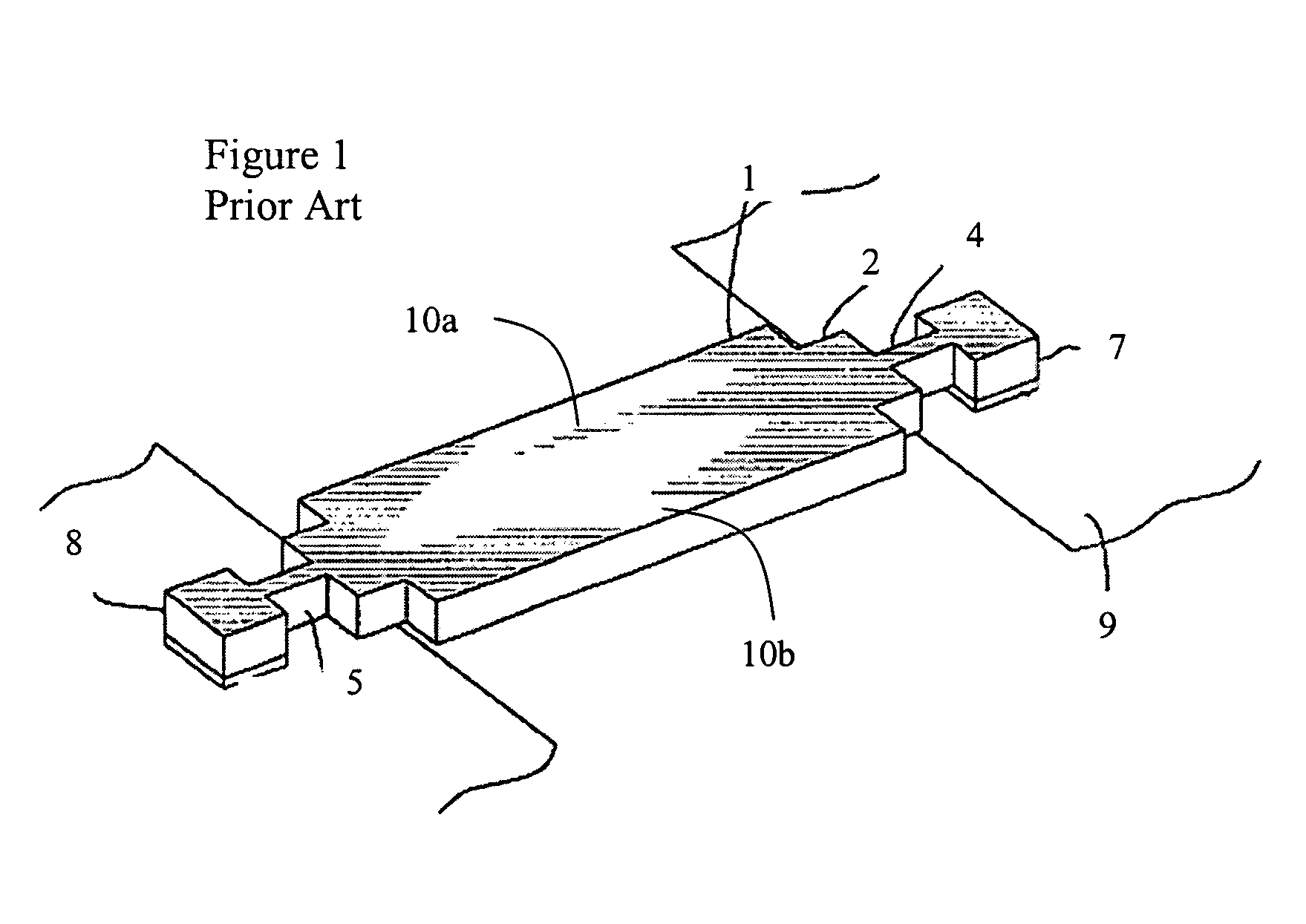
Unfortunately, when the device is switched between ports at the extremes of the devices rotational path, the intermediate ports receive light for fractions of a millisecond as the mirror 1 sweeps the optical beam past these ports, thereby causing undesirable optical transient or dynamic cross-talk.
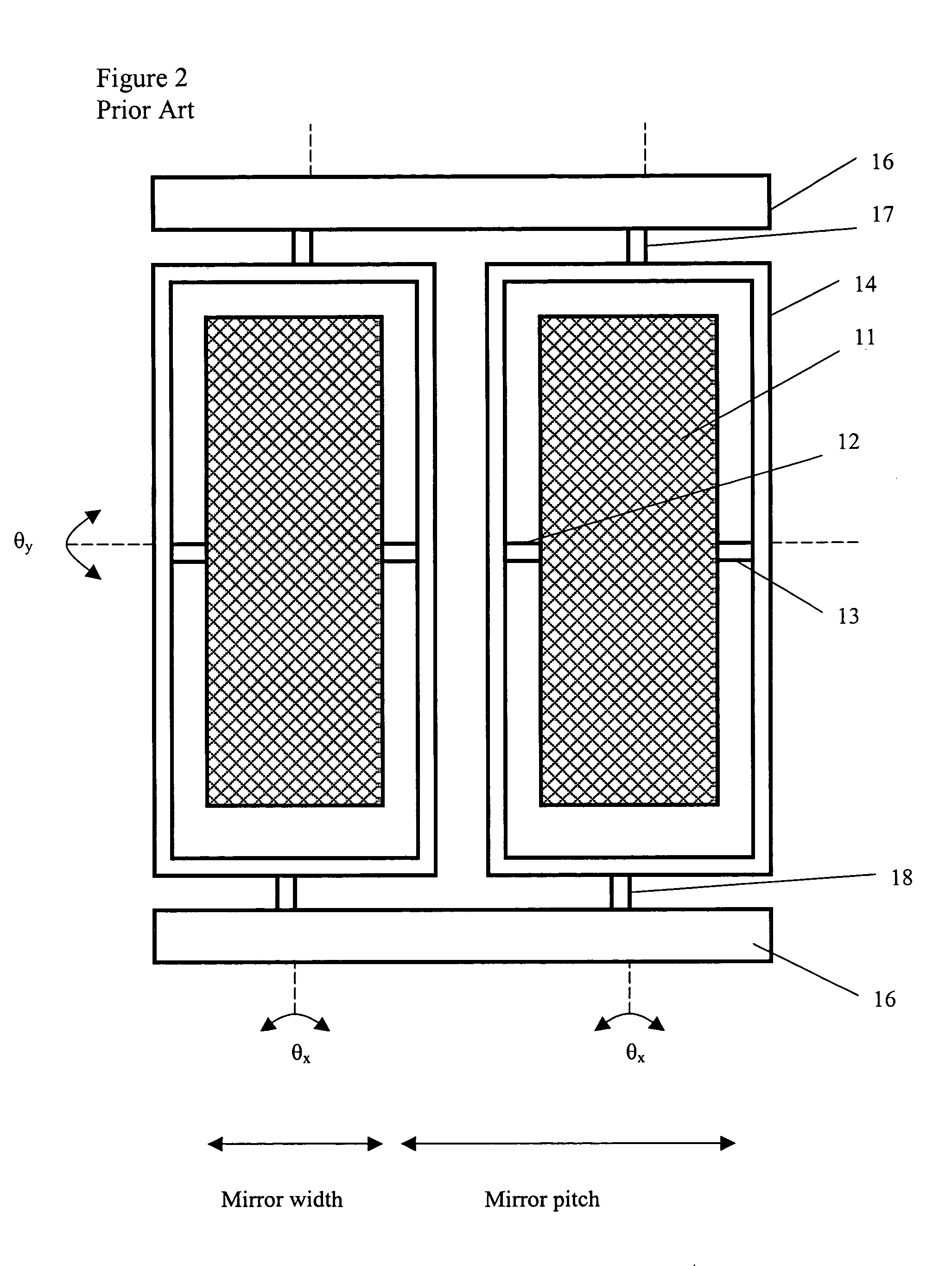
Unfortunately, an external gimbal ring greatly limits the number of mirrors that can be arranged in a given area and the relative proximity thereof, i.e. the fill factor.
Moreover, the external gimbal ring may cause unwanted reflections from light reflecting off the support frame.
Unfortunately, these types of mirror devices require costly multi-step fabrication processes, which increase costs and result in low yields, and rely on four different pairs of electrodes for actuation.

Method used


Image

  • Electrode configuration for piano MEMs micromirror
  • Electrode configuration for piano MEMs micromirror
  • Electrode configuration for piano MEMs micromirror

Examples


Embodiment Construction

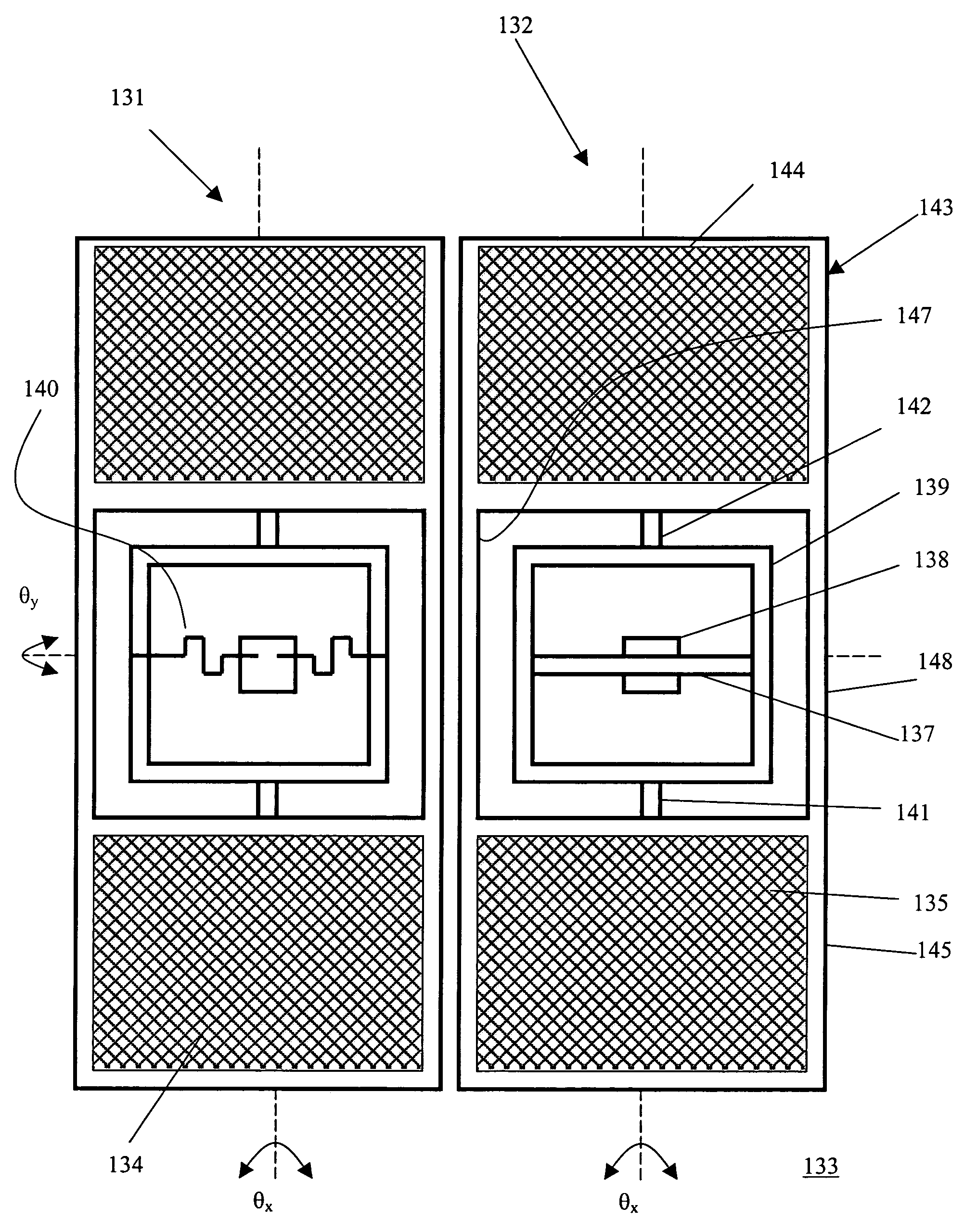
[0042]An array of “Piano” MEMs mirror devices 21, 22 and 23, which pivot about a single axis of rotation θy above a substrate 25, is illustrated in FIGS. 3, 4 and 5. Each mirror device 21, 22 and 23 includes a pivoting member or platform 26 defined by first and second substantially-rectangular planar supporting regions 27 and 28 joined by a relatively-thin substantially-rectangular brace 29 extending therebetween. Typically, each planar surface is coated with a reflective coating, e.g. gold, for simultaneously reflecting a pair of sub-beams of light traveling along parallel paths, as will be hereinafter discussed. Each brace 29 acts like a lever and is pivotally mounted to anchor posts 30 and 31 via first and second torsional hinges 32 and 33, respectively. The anchor posts 30 and 31 extend upwardly from the substrate 25. The ends of the first torsional hinge 32 are connected to the anchor post 30 and the brace 29 along the axis θy. Similarly, the ends of the second torsional hinge ...


PUM


Abstract

A micro-electro-mechanical (MEMs) mirror device for use in an optical switch is disclosed. A “piano”-style MEMs device includes an elongated platform pivotally mounted proximate the middle thereof by a torsional hinge. The middle portion of the platform and the torsional hinge have a combined width less than the width of the rest of the platform, whereby several of these “piano” MEMs devices can be positioned adjacent each other pivotally mounted about the same axis with only a relatively small air gap therebetween. In a preferred embodiment of the present invention specially designed for wavelength switching applications, a greater range of arcuate motion for a mirror mounted thereon is provided by enabling the platform to rotate about two perpendicular axes. The MEMs mirror device according to the preferred embodiment of the present invention enables the mirror to tilt about two perpendicular axes, by the use of an “internal” gimbal ring construction, which ensures that a plurality of adjacent mirror devices have a high fill factor, without having to rely on complicated and costly manufacturing processes.

Description

CROSS-REFERENCE TO RELATED APPLICATIONS[0001]The present application is a continuation-in-part of U.S. patent application Ser. No. 10 / 445,360, filed May 27, 2003 which claims priority from U.S. patent application No. 60 / 383,106 filed May 28, 2002, which are both incorporated herein by reference. The present application also claims priority from U.S. patent applications Nos. 60 / 504,210 filed Sep. 22, 2003; 60 / 537,012 filed Jan. 20, 2004; and 60 / 558,563 filed Apr. 2, 2004, which are all incorporated herein by reference.TECHNICAL FIELD[0002]The present invention relates to a micro-electro-mechanical (MEMs) mirror device for use in an optical switch, and in particular to an electrode arrangement for a 2d gimbal ring MEMs mirror device.BACKGROUND OF THE INVENTION[0003]Conventional MEMs mirrors for use in optical switches, such as the one disclosed in U.S. Pat. No. 6,535,319 issued Mar. 18, 2003 to Buzzetta et al, to redirect beams of light to one of a plurality of output ports include an...

Claims


Application Information

Patent Timeline
Patent Type & Authority Patents(United States)
IPC IPC(8): B81B3/00G02B6/35G02B26/08
CPCB81B3/0062G02B6/3584G02B26/0841B81B2201/042G02B6/3518G02B6/3544G02B6/356G02B6/357Y10S359/904
Inventor MILLER, JOHN MICHAELMA, YUANKEYWORTH, BARRIEJIN, WENLINHESS, DAVID R.
Owner LUMENTUM OPERATIONS LLC
Learn More