
Impact absorbing composite

Inactive Publication Date: 2005-11-29
GOLDFINE ANDREW A
View PDF76 Cites 207 Cited by
  • Summary
  • Abstract
  • Description
  • Claims
  • Application Information

AI Technical Summary

Problems solved by technology

These types of contact sports and high-impact activities often cause application of high energy impacts against discrete portions of the human body that often cause bruises and even more serious injuries, such as broken or fractured bones.
Besides the noted contact sports and high energy impact activities, there are a number of other activities that, in the event of an accident or spill, may cause injury to the body.
Marketing of such shoe inserts is often targeted to participants in sports, such as basketball, football, soccer, and running, where repetitive impacts during each successive step may cause injuries to the foot and lower leg, such as sprains, shin splints, and even broken bones.
However, many of these new impact absorbing materials merely amount to laminates of multiple continuous layers.
Continuous layers suffer from a couple of different problems, typically.
For example, continuity of a layer will often inhibit the ability of adjacent layers to fully exhibit properties, such as elasticity, of the adjacent layers.
Also, where one continuous layer is fairly rigid and an adjacent continuous layer is fairly flexible, the fairly rigid continuous layer will inhibit the ability of the flexible continuous layer to exhibit the flexibility.
Also, to the degree that impact absorbance depends upon elevated rigidity in one of the continuous layers, existing impact absorbing materials consequently sacrifice flexibility and the ability to conform to complex three-dimensional shapes in favor of enhanced impact absorbance capability, or, alternatively, sacrifice impact absorbing capability in favor of enhanced flexibility and ability to conform to complex three-dimensional surfaces.
One reason that manufactures of impact absorbing materials have come to rely primarily upon continuous layers is that manufacture of impact absorbing materials with discontinuous layers has been traditionally considered to be technically impractical and expensive.
While such improvements have enhanced the knowledge base with regard to impact absorbing materials, these approaches have typically enhanced, sometimes dramatically, the cost of impact absorbing materials to the consumer, while still failing to uncouple the property interdependence existing between continuous layers in existing impact absorbing materials.
Therefore, despite these industry developments, existing impact absorbing materials that are formed of multiple continuous layers continue to sacrifice flexibility and conformability in favor of impact absorbance, or continue to sacrifice impact absorbance in favor of flexibility and conformability.
While such an impact absorbing material does, theoretically, have many benefits, practical considerations limit the actual capabilities of such a material.
For example, the volume of fluid within the envelope must typically be limited due to the density of the fluid contained within the envelope and the consequent overall weight of the fluid-filled envelope.
Such limitations of the envelope volume necessarily limit the thickness of the fluid layer within the envelope, which thereby detracts from the impact absorbing capabilities of the fluid-filled envelope.
While many enhancements have been developed and introduced to consumers of impact absorbing materials, these improved impact absorbing materials continue to suffer from a number of drawbacks.
For example, technical improvements within individual continuous layers of existing impact absorbing materials have caused great increases in the costs of these impact absorbing materials to consumers.

Method used


Image

  • Impact absorbing composite
  • Impact absorbing composite
  • Impact absorbing composite

Examples


Embodiment Construction

[0030]The present invention generally relates to an impact absorbing composite. More specifically, the present invention relates to an impact absorbing composite that is formed of separate, discrete, and independent impact absorbing members. The impact absorbing composite is capable of conforming to complex three-dimensional surfaces. Also, the impact absorbing composite is capable of both absorbing and dissipating energy from an impact that is applied against the impact absorbing composite. The present invention further relates to a method of making the impact absorbing composite.

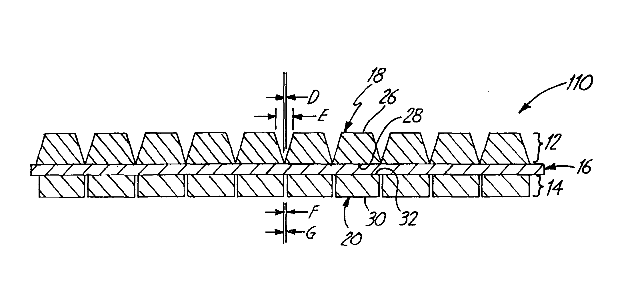
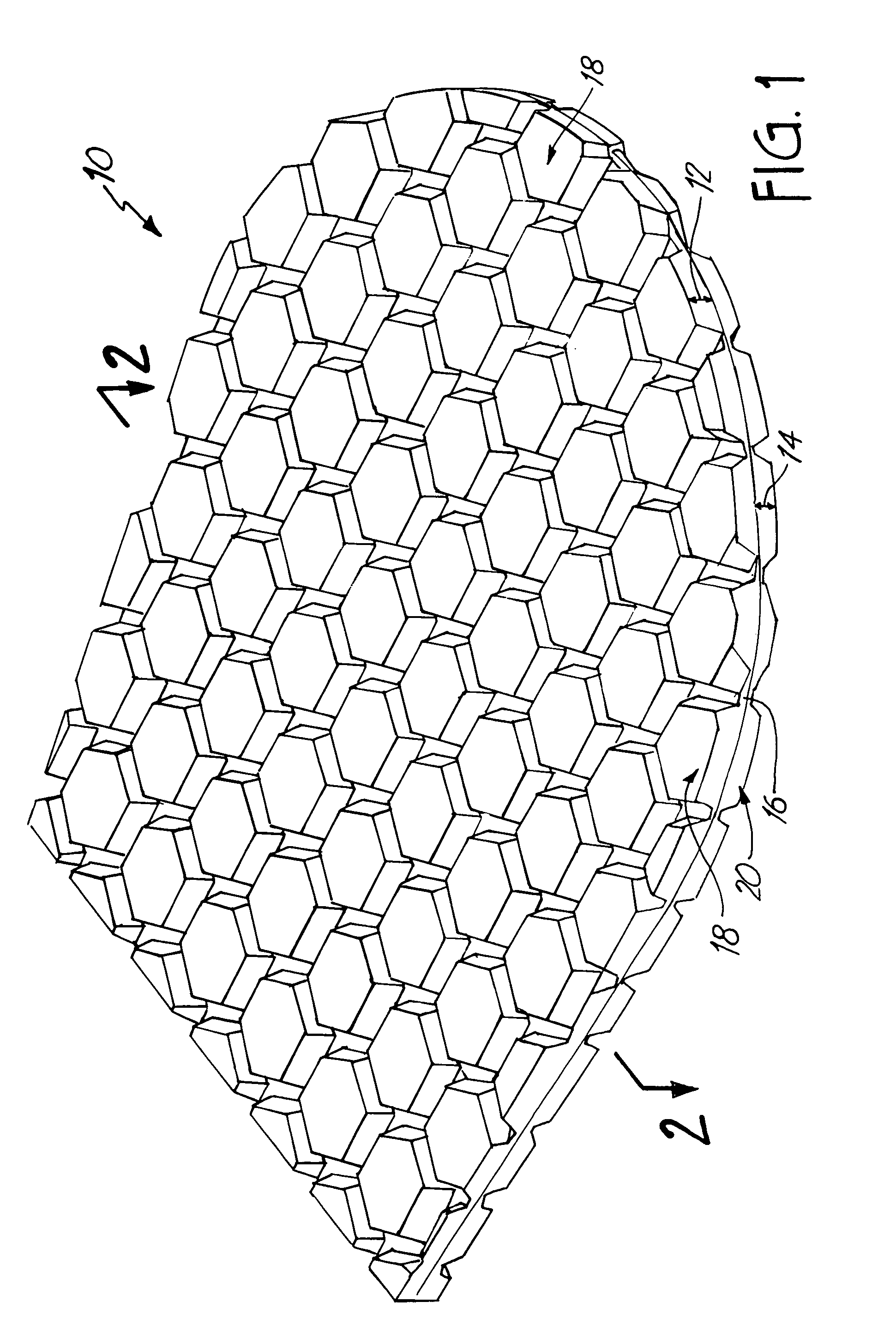
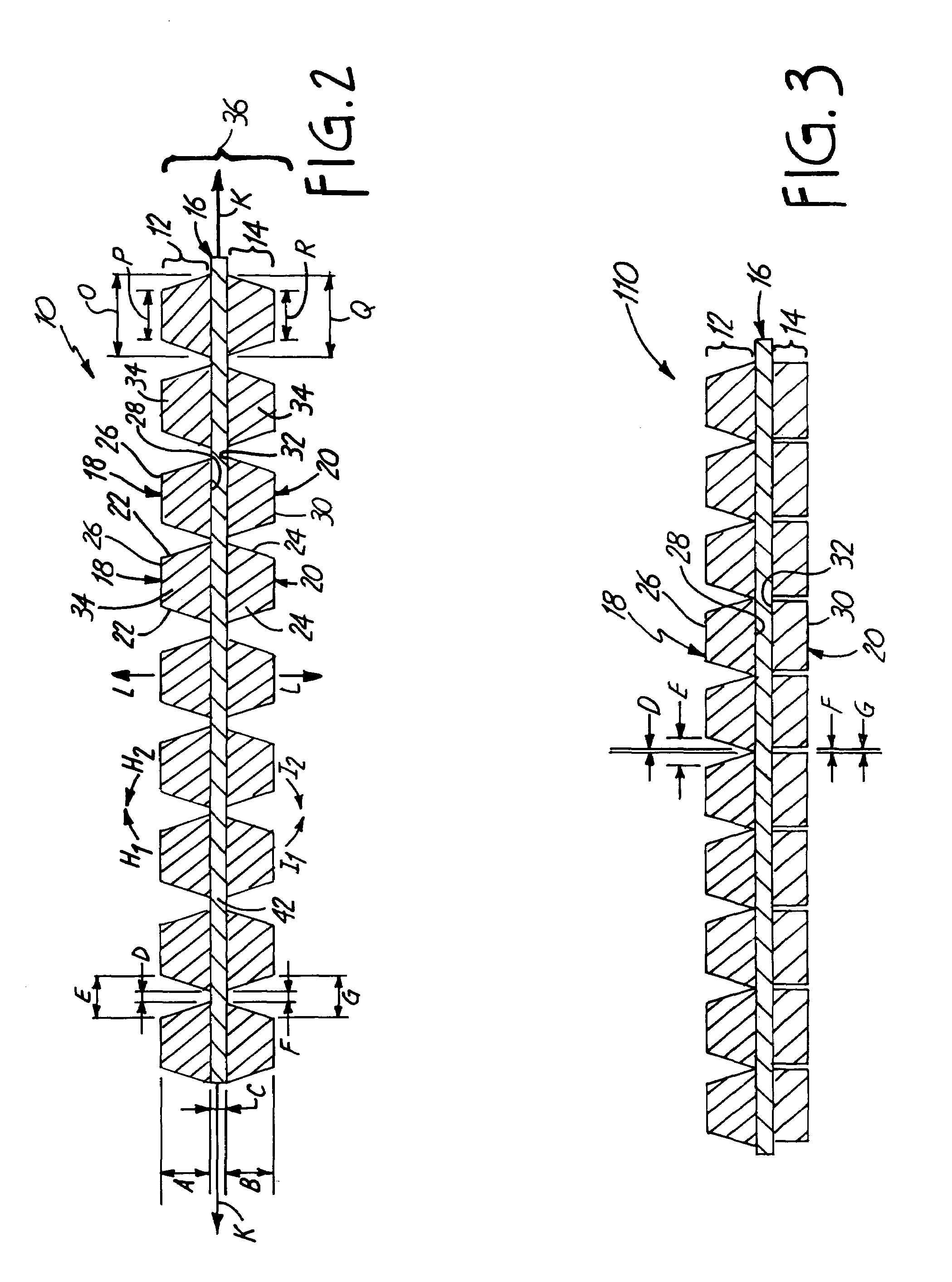
[0031]The impact absorbing composite of the present invention is generally depicted at 10 in FIG. 1. The impact absorbing composite 10 includes a first impact absorbing layer 12, a second impact absorbing layer 14, and a flexible substrate web or layer 16 that is located between the first impact absorbing layer 12 and the second impact absorbing layer 14. The first impact absorbing layer 12 is formed of a ...


PUM

PropertyMeasurementUnit
Massaaaaaaaaaa
Massaaaaaaaaaa
Fractionaaaaaaaaaa

Abstract

An impact absorbing composite structure (10), the impact absorbing composite structure including a plurality of impact absorbing members (18) and a flexible layer (16), each impact absorbing member (18) integral with the flexible layer (16).

Description

BACKGROUND OF THE INVENTION[0001]The present invention generally relates to an impact absorbing composite. More specifically, the present invention relates to an impact absorbing composite that is formed of separate, discrete, and independent impact absorbing members. The impact absorbing composite is capable of conforming to complex three-dimensional surfaces. Also, the impact absorbing composite is capable of both absorbing and dissipating energy from an impact that is applied against the impact absorbing composite. The present invention further relates to a method of making the impact absorbing composite.[0002]Enhanced participation in contact sports, such as football, soccer, and rugby, along with enhanced participation in other high impact energy activities, such as inline skating and white water kayaking, has fueled the demand and need for improved impact absorbing materials. These types of contact sports and high-impact activities often cause application of high energy impact...

Claims


Application Information

Patent Timeline
IPC IPC(8): A41D31/00B29C44/12B29C67/20B32B3/16
CPCA41D31/0061B29C44/1214A41D13/015Y10S206/814Y10T428/24331Y10T428/24347Y10T428/24339Y10T428/24504Y10T428/24322Y10T428/24496Y10T428/2457Y10T428/24512A41D31/245
Inventor GOLDFINE, ANDREW A.
Owner GOLDFINE ANDREW A
Learn More