
Multiple, permanent-magnet rotor for a rotating electrical machine, and a method for producing same

a technology of permanent magnet rotor and rotating electrical machine, which is applied in the direction of dynamo-electric machines, magnetic circuit rotating parts, and magnetic circuit shape/form/construction. it can solve problems such as difficulties in installation and securing of magnets

Inactive Publication Date: 2005-11-29
SIEMENS AG
View PDF56 Cites 13 Cited by
  • Summary
  • Abstract
  • Description
  • Claims
  • Application Information

AI Technical Summary

Problems solved by technology

If the rotors of machines such as these are constructed using flux concentration, this involves difficulties in the installation and securing of the magnets.

Method used


Image

  • Multiple, permanent-magnet rotor for a rotating electrical machine, and a method for producing same
  • Multiple, permanent-magnet rotor for a rotating electrical machine, and a method for producing same
  • Multiple, permanent-magnet rotor for a rotating electrical machine, and a method for producing same

Examples


Embodiment Construction

[0020]The invention discloses a rotor construction such that the permanent magnet can be stored without exerting large amounts of force.

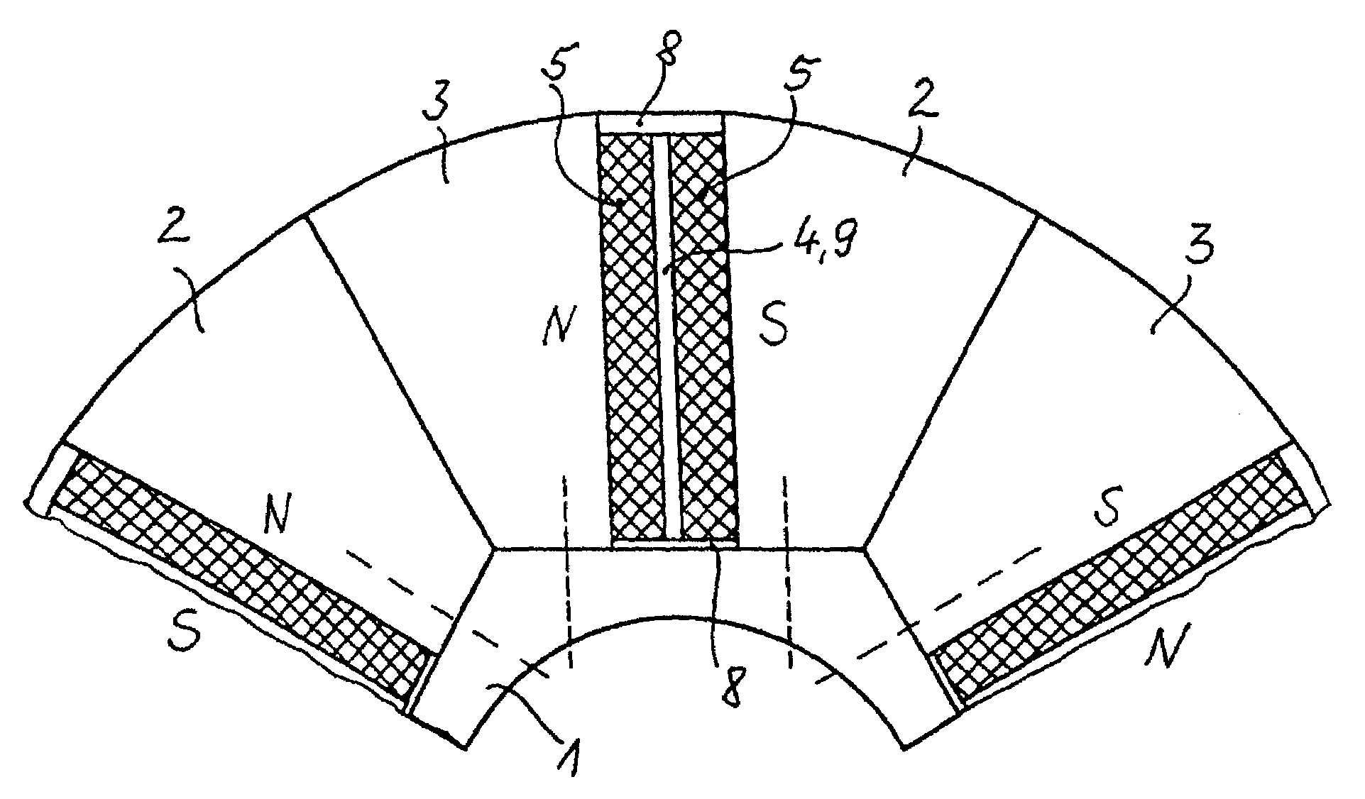
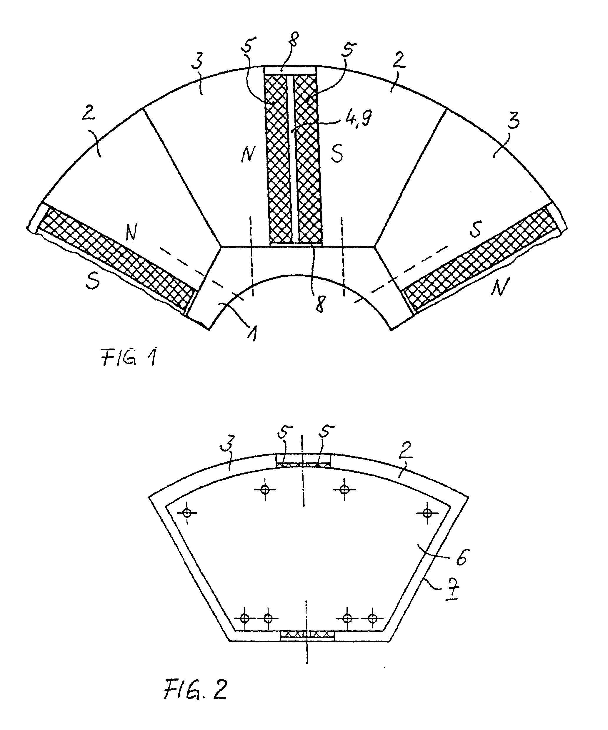
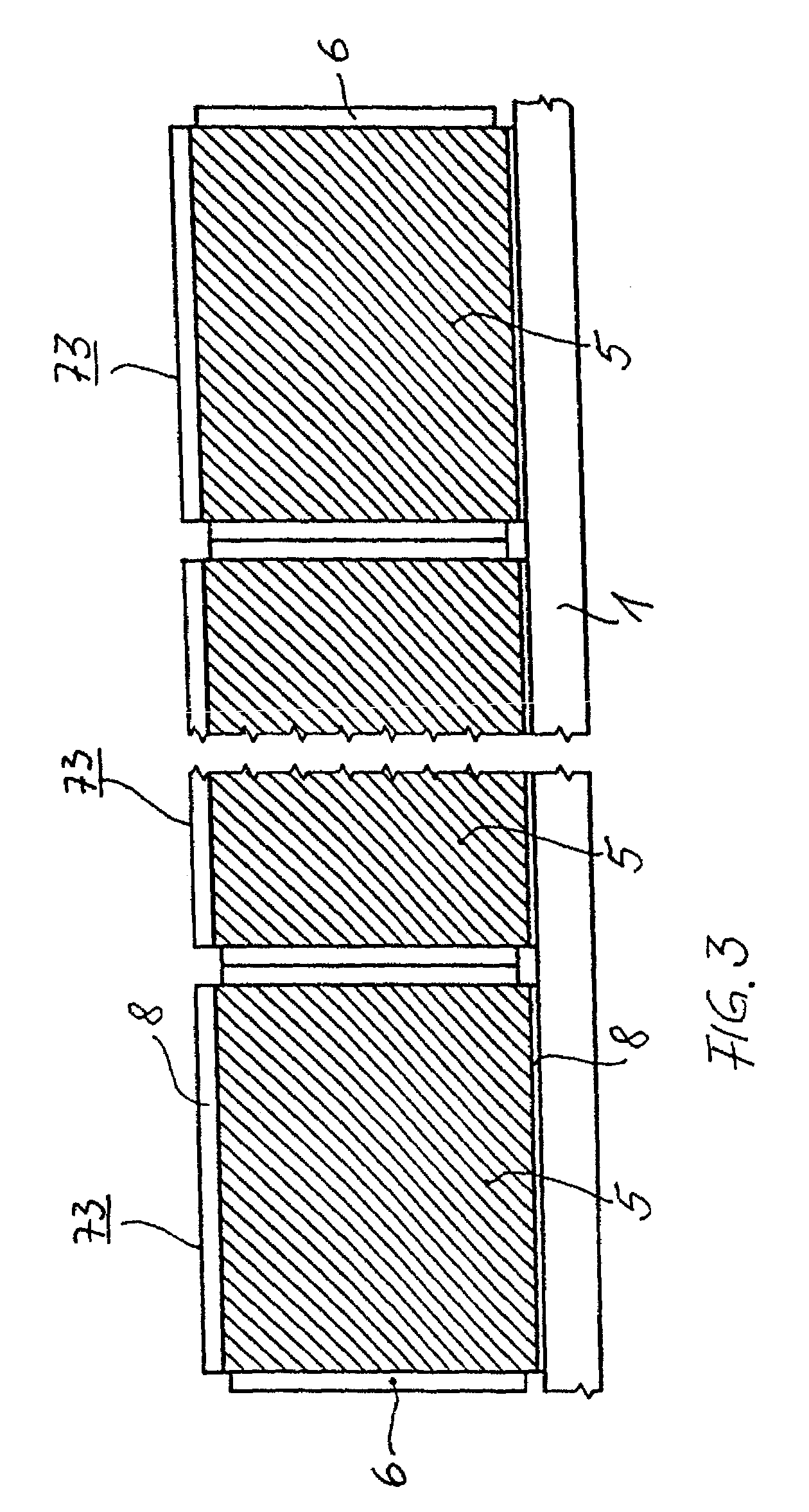
[0021]This is achieved by providing for each yoke to be subdivided in the circumferential direction into two half yokes, each of which extend over half of one pole pitch. Two mutually adjacent half-yokes of two yokes are arranged alongside one another and are in each case connected by means of end plates to form a pole element. Each pole element is fixed on its own on the rotor body. In this case, the pole elements can be designed such that either each of the two half-yokes is fitted with permanent magnets on its surface facing a slot-like intermediate space, or such that only one of the two half-yokes is fitted with permanent magnets on the surface facing the other half-yoke. If the permanent magnets are arranged on the corresponding surfaces of the half-yokes and of the pole elements on the rotor body, it is expedient for the magnets to be fitted ...


PUM


Abstract

In order to allow a rotating electrical machine, which uses a permanent-magnet rotor with a flux-concentration construction for a rated power of more than 100 kW, to be assembled as easily as possible, two mutually adjacent half-yokes of two poles as well as magnets arranged between them in each case form a pole element which can be fixed on its own on the rotor body.

Description

CLAIM FOR PRIORITY[0001]This application claims priority to International Application No. PCT / DE00 / 00853 which was published in the German language on Sep. 28, 2000.TECHNICAL FIELD OF THE INVENTION[0002]The invention relates to the field of rotating electrical machines, and in particular, to the design configuration of rotor cores which are fitted with permanent magnets using a flux concentration construction.BACKGROUND OF THE INVENTION[0003]Special permanent magnets, i.e., which are matched to the stringent requirements of electrical machines, have been successfully developed. Such magnets are used to produce the rotating magnetic field in the rotating electrical machines. Various options for the arrangement of the permanent magnets in the rotor or in the stator have been developed for motors and generators with rated powers up to 30 kW at 3000 rpm. In this case, “flux concentration construction” has been found to be the technically better solution above a rated power of several hu...

Claims


Application Information

Patent Timeline
Patent Type & Authority Patents(United States)
IPC IPC(8): H02K1/27H02K1/28
CPCH02K1/2766H02K1/28
Inventor SCHUERING, INGO
Owner SIEMENS AG
Learn More