Electrical connector for use in transmitting a signal

a technology for electrical connectors and signals, applied in the direction of fixed connections, manufacturing tools, coupling device connections, etc., can solve the problems of difficult to completely surround and shield contacts, complicated configuration of electrical connectors, and increased number of parts, so as to reduce crosstalk and reduce the occurrence of crosstalk , the effect of preventing degradation of transmission characteristics

Inactive Publication Date: 2005-12-06
JAPAN AVIATION ELECTRONICS IND LTD
View PDF11 Cites 77 Cited by
  • Summary
  • Abstract
  • Description
  • Claims
  • Application Information

AI Technical Summary

Benefits of technology

[0007]It is an object of this invention to provide an electrical connector which is capable of forming a pseudo coaxial line in a simple structure so as to reduce occurrence of crosstalk between contacts and to prevent degradation of transmission characteristics and which requires a reduced number of parts.

Problems solved by technology

However, it is difficult to completely surround and shield the contacts.
In order to form such a coaxial structure, however, the electrical connector inevitably has a complicated configuration and requires an increased number of parts.

Method used


Image

  • Electrical connector for use in transmitting a signal
  • Electrical connector for use in transmitting a signal
  • Electrical connector for use in transmitting a signal

Examples


first embodiment

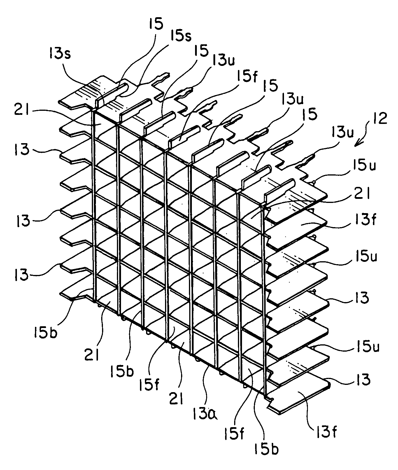
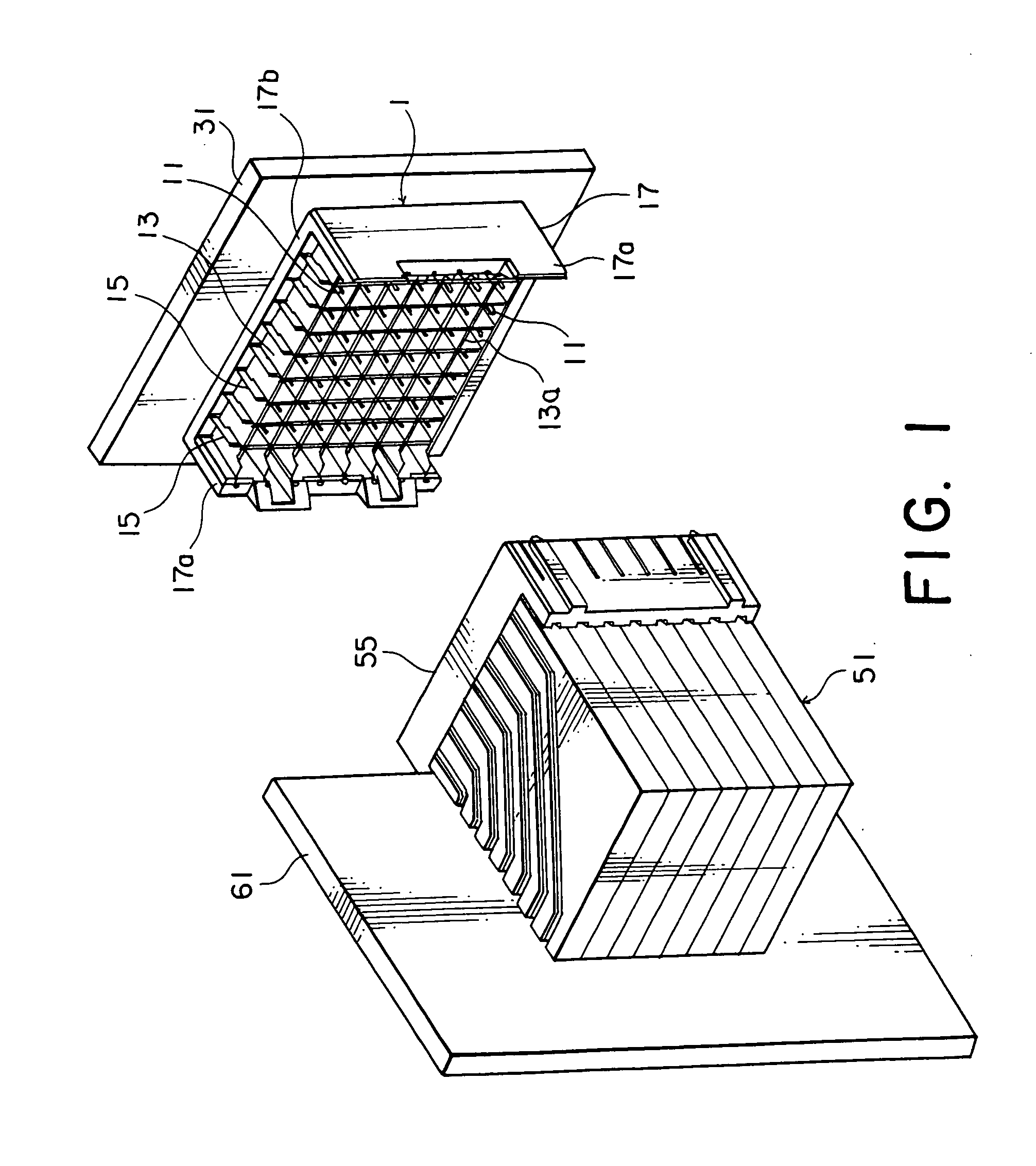
[0022]Referring to FIGS. 1 and 2, a connector 1 according to this invention comprises a plurality of conductive contacts (signal contacts) 11 arranged in a matrix fashion, i.e., in a vertical direction and in a horizontal direction, with a predetermined space left from one another, a ground member 12 arranged between adjacent ones of the contacts with a preselected space left from each contact, and an insulator 17 holding the contacts 11 and the ground member 12.

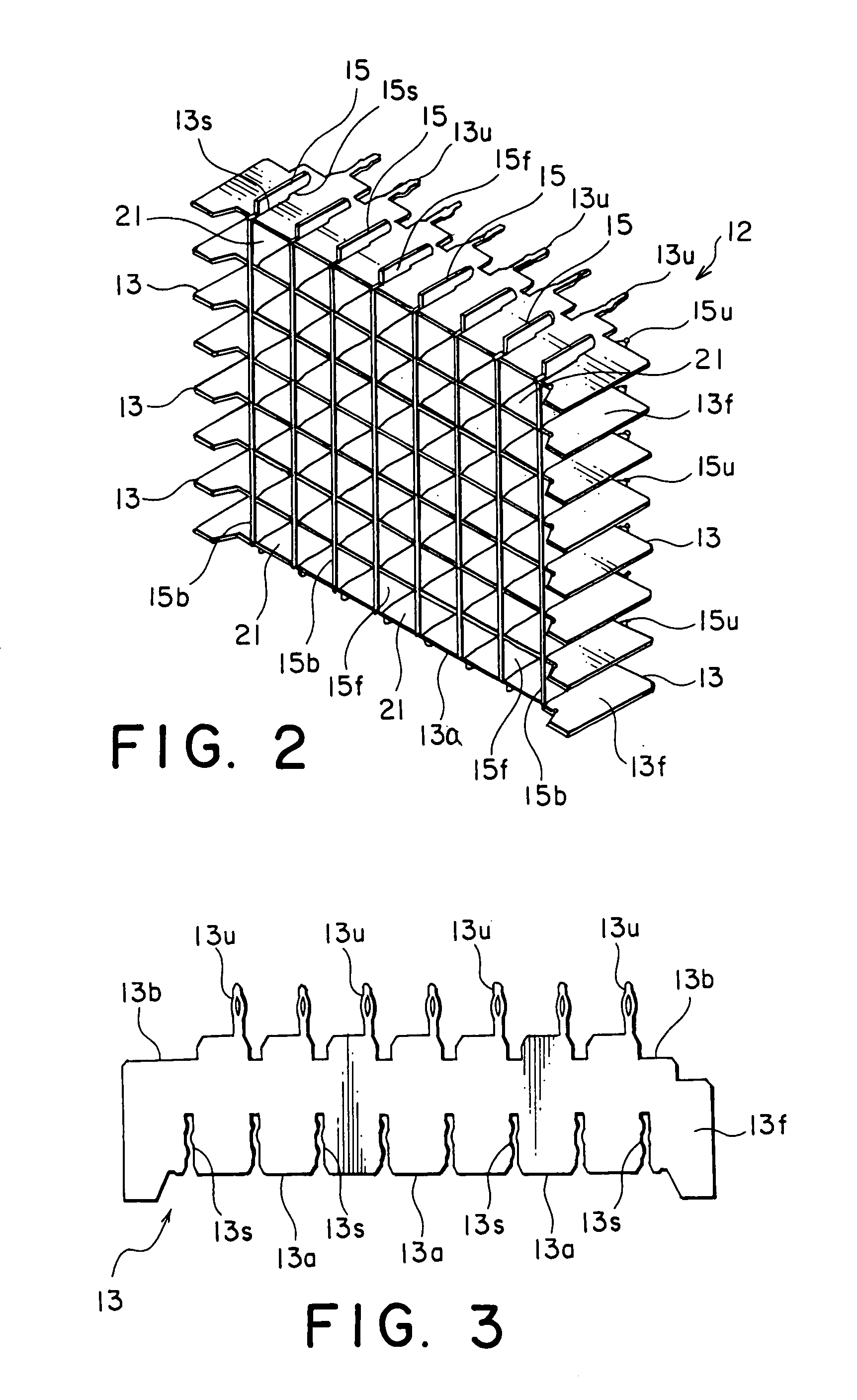
[0023]Each of the contacts 11 in this embodiment is a pin contact for signal transmission and reception. The ground member 12 comprises a plurality of first ground plates 13 and a plurality of second ground plates 15. Each of the first ground plates 13 is formed as an elongate plate by punching a thin conductive plate using a punch press. Likewise, each of the second ground plate 15 is formed by the similar process as an elongate plate.

[0024]In this embodiment, the first ground plates 13, eight in number, are arranged in par...

second embodiment

[0053]In the second embodiment, the first additional slit portions 13g are formed in the first ground plate 13 to form the first contacting portions 14. Alternatively or additionally, the second ground plate 15 may be provided with a plurality of additional slit portions similar to the first additional slit portions to form second contacting portions similar in shape to the first contacting portions 14.

[0054]In the first and the second embodiments, description has been directed to the case where the first and the second ground plates 13 and 15 have the first and the second contacting portions 13z and 15z, respectively. Alternatively, only one of the first and the second ground plates 13 and 15 may be provided with the contacting portions.

[0055]In the foregoing embodiments, a plurality of the first and the second contacting portions 13z and 15z are formed. Alternatively, each of the first and the second contacting portions 13z and 15z may be formed at only one position of each of the...


PUM

PropertyMeasurementUnit
conductiveaaaaaaaaaa
speedaaaaaaaaaa
rectangular shapeaaaaaaaaaa

Abstract

An electrical connector comprises a plurality of conductive contacts arranged in a matrix pattern with a space left from one another and a conductive ground member disposed in the space. The ground member comprises a plurality of first ground plates and a plurality of second ground plates combined with the first ground plates. Each of the first ground plates has a plurality of first slit portions. Each of the second ground plates has a plurality of second slit portions. The contacts are received in one-to-one correspondence in a plurality of contact receiving portions defined by combining the first and the second ground plates in a lattice fashion in the state that the second and the first ground plates are inserted in the first and the second slit portions, respectively. Each of the first slit portions has at least one contacting portion contacted with the second ground plate inserted therein.

Description

BACKGROUND OF THE INVENTION[0001]This invention relates to an electrical connector for use in transmitting a signal and, in particular, to an electrical connector for use in transmitting a high-speed signal.[0002]For example, an electrical connector of the type is disclosed in Japanese Patent Application Publication (JP-A) No. 2002-117938 (Reference 1). The electrical connector comprises a plurality of pin contacts, a housing holding the contacts, and a plurality of ground plates.[0003]The ground plates includes first and second ground plates. One of the first and the second ground plates has a first contacting portion connected to at least one of the contacts and a second contacting portion connecting the first and the second ground plates to each other. The first ground plate is placed between adjacent ones of the contacts. The second ground plate extends in a direction intersecting with the first ground plate and is placed between adjacent ones of the contacts.[0004]Another elect...

Claims


Application Information

Patent Timeline
Patent Type & Authority Patents(United States)
IPC IPC(8): H01R12/16H01R13/514H01R13/648
CPCH01R23/688H01R12/585H01R13/514H01R12/52Y10T409/302464H01R13/6471H01R13/6583H01R13/6594H01R12/00
Inventor TOKUNAGA, TAKASHI
Owner JAPAN AVIATION ELECTRONICS IND LTD
Why Eureka
Try Eureka