[0013]With this vision assisting apparatus, by bending the optical path upwards in an inverse U-shape, it is possible, without increasing the length in the horizontal direction between the light entry and the light exit, to make the optical path sufficiently long for setting the optical system. Accordingly, the light entry can be disposed close to the wearer (user)'s dominant eye, which makes it possible to provide a vision assisting apparatus where little
parallax is experienced. In addition, with the casing for forming the inversely U-shaped optical path, a part that is close to the eye during use can be made in an inverse U-shape, so that the vision assisting apparatus of this invention thoroughly prevents the periphery of the user's eye from becoming hidden by the casing, and the user'
s expression can be easily seen by others. Also, the casing is inversely U-shaped in the upward direction, during using, the center of gravity of the casing is positioned close to the face without the casing being disposed very far from the brow. Accordingly, it is possible for the vision assisting apparatus to be worn stably with there being little vibration in the image, even when the wearer moves. In this way, by using an optical path in an inverse U-shape, it is possible to provide a vision assisting apparatus that can be worn stably and with which little
parallax is experienced, even when looking at a
proximate object. Also, it is possible to provide a vision assisting apparatus that feels natural to use and hardly hides the user'
s expression.
[0014]In addition, with the vision assisting apparatus of the present invention, the distance between the light entry and the light exit is narrow, so that when the light exit is disposed almost directly in front of one of the wearer's eyes, the light entry can be prevented from hiding the wearer's other eye. Accordingly, it is possible to dispose the light exit, that is, the ocular lens, almost directly in front of one of the wearer's eyes without sacrificing the
field of view of the wearer's other eye. This means that it is possible to provide a vision assisting apparatus which can be used without sacrificing the
field of view of the wearer's other eye, even when the light exit is disposed so that the wearer does not have to move his or her eye up and down. In this way, the vision assisting apparatus places even less burden on the wearer.
[0015]In addition, the vision assisting apparatus of the present invention has an inversely U-shaped optical path, so that arrangement of the light entry and the light exit can be desired to be in the horizontal direction. Accordingly, the light entry and the light exit can be aligned approximately horizontally with no difference in the heights of the position of the wearer's eye and the light entry, which can reliably prevent
parallax from being experienced in the vertical direction, especially when looking at a
proximate object.
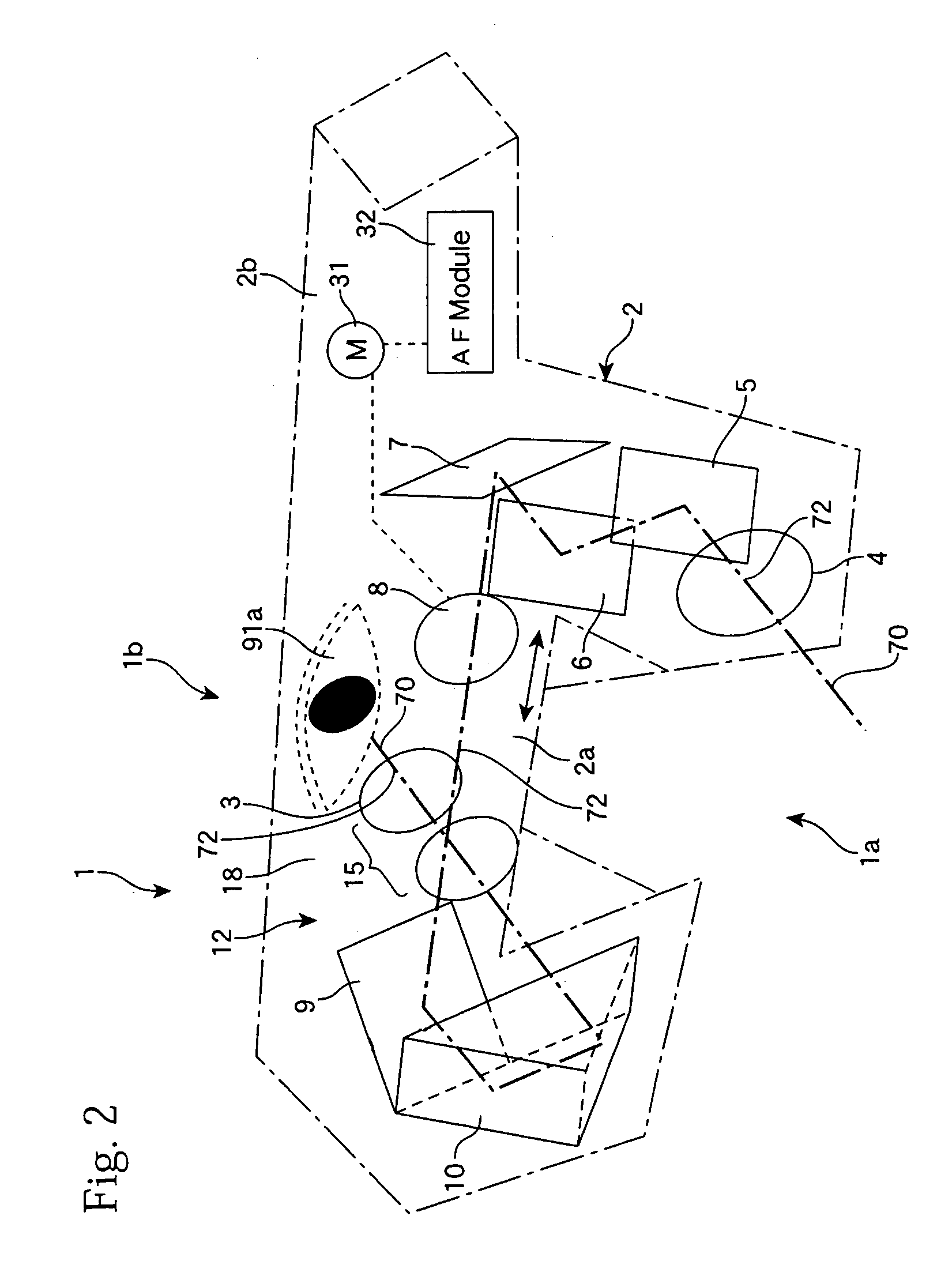
[0016]In this way, by making the optical path inversely U-shaped, the vision assisting apparatus of the present invention can provide sufficient optical distance between the light entry and the light exit while making it possible to adjust the actual distance. Accordingly, a variety of optical systems for assisting eyesight or vision, such as an optical system for correcting myopia,
hypermetropia,
astigmatism, or the like, or assisting or compensating for weak
sight can be arranged using the optical path. In particular, this apparatus is suited to housing a magnifying optical system for the weak-sighted, which tends to include a large number of lenses. That is, the vision assisting apparatus of the present invention is suited to housing a magnifying optical system for magnify the image from the light entry by using the optical path and output an erect
real image from the light exit, thereby providing a user with a
telescope function or
magnifying glass (magnifier). With this vision assisting apparatus, a magnifying optical system is housed and the light entry can be disposed in the center of the wearer's face, so that an image is obtained where one eye looks out from the center of the face. In addition, the light exit is positioned close to the
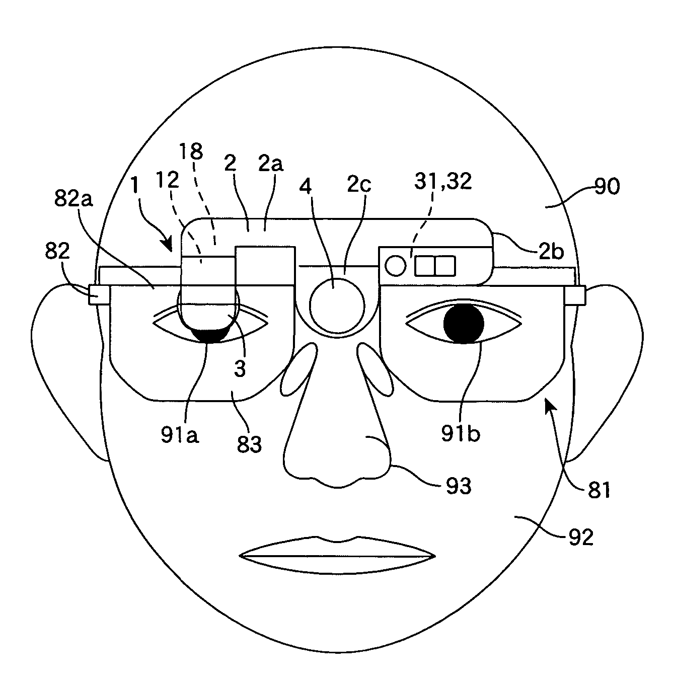
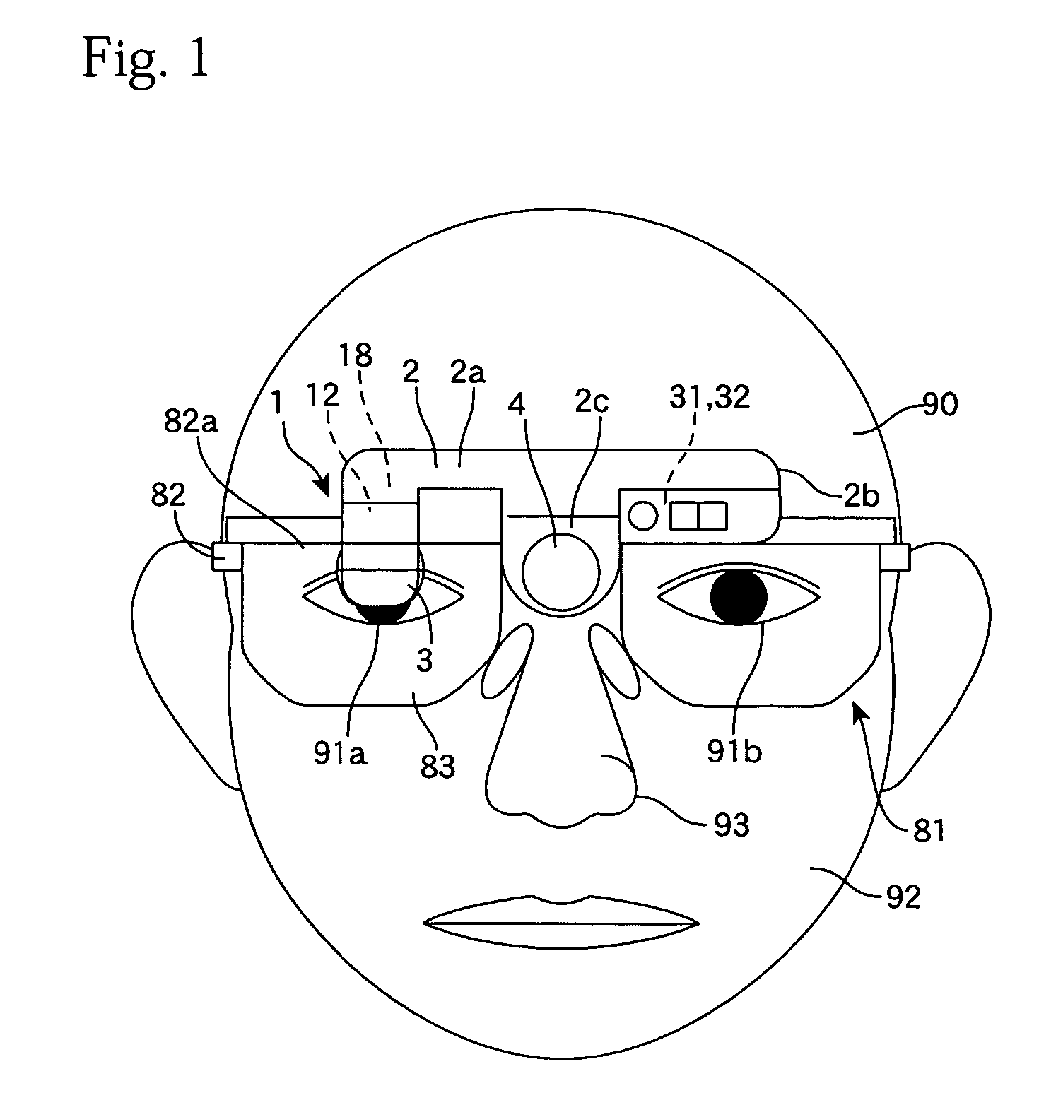
nose, so that both ends and / or the periphery of the wearer's eyes can be seen, resulting in the magnifier of this invention that allows the wearer's expression to be easily discerned. Accordingly, an image that is approximately the same as that obtained when looking with both eyes can be obtained with one eye, so the magnifier that leaves both hands free and has little parallax in the horizontal direction can be provided. That is, the vision assisting apparatus of this invention includes a construction where the light entry and light exit are aligned approximately horizontally and the light entry is positioned in the approximate center of the wearer's face, with having a magnifying function, that makes it easy for the user to see, and which places little burden on the user.
[0017]In addition in this vision assisting apparatus, it is possible to provide space for providing the optical path with a mechanism that can automatically adjust the focus of the magnifying optical system, that is, an auto-focus module, so that images with no blurring from near positions to far positions can be stably supplied from the light exit to the user's eye.
[0018]The inversely U-shaped optical path can be extended as necessary upwards from the position of the eye. However, in order to wear the apparatus stably, it is preferable for the dimensions of the casing in the vertical direction to be set so that the casing fits into the range from the wearer's eye to the brow or
forehead. The vision assisting apparatus of the present invention can be attached to a helmet, a hat, a hair band, etc, and can be supported by the head, the brow, the ears, and / or the
nose. In addition, it is possible to use a normal eyeglass frame as a means for supporting, so that the apparatus can be worn stably using the ears and
nose in the same way as normal eyeglasses.
