
Coil conductor with trace conductors for a thin-film magnetic head

a thin-film magnetic head and conductor technology, applied in the field of thin-film magnetic head elements, can solve the problems of no improvement of characteristics, and difficulty in writing and reading data operations, and achieve the effect of reducing the inductance of the coil

Inactive Publication Date: 2005-12-06
SAE MAGNETICS (HK) LTD
View PDF3 Cites 0 Cited by
  • Summary
  • Abstract
  • Description
  • Claims
  • Application Information

AI Technical Summary

Benefits of technology

[0007]It is therefore an object of the present invention to provide a thin-film magnetic head, whereby a coil inductance can be reduced without inviting difficulty in manufacturing and deterioration in characteristics.
[0009]The magnetic fields counter with each other between the lower conductor layer of the first trace conductor and the upper conductor layer of the second trace conductor and also between the lower conductor layer of the second trace conductor and the upper conductor layer of the first trace conductor to greatly decrease stray inductances caused by the currents. On the other hand, due to the reversed current flowing, the electrical fields strengthen with each other between the lower conductor layer of the first trace conductor and the upper conductor layer of the second trace conductor and also between the lower conductor layer of the second trace conductor and the upper conductor layer of the first trace conductor to increase stray capacitances. Thus, the stray inductance of the trace conductors connected to the coil conductor can be decreased. Therefore, it is possible to flow a write current having a short rising time and a high current value through the coil conductor with maintaining a profile of rectangular wave shape input pulses as much as possible. Due to the short rising time, correct writing operations can be expected even if the write frequency is high as 300 MHz for example. Of course, since no change nor modification of the shape and size of the coil conductor is required, no difficulty in manufacturing and no deterioration in characteristics will be invited.
[0011]It is also preferred that the first and second trace conductors are formed substantially in line to connect the coil conductor with the first and second connection bumps. By this configuration, the length of the first and second trace conductors can be shortened resulting the stray inductance to decrease accordingly.

Problems solved by technology

If the wave shape of current flowing through the inductive write head element of the thin-film magnetic head is deformed, magnetic patterns written in a magnetic medium will become distorted and thus write and read operations of data will become difficult.
However, if the number of turns of the coil is reduced to decrease the inductance, magnetic force generated from the coil will decrease causing no improvement of the characteristics.
Also, if the size of the coil is reduced by narrowing a coil pitch, difficulty in fabrication of the coil and problems of heating may occur.

Method used


Image

  • Coil conductor with trace conductors for a thin-film magnetic head
  • Coil conductor with trace conductors for a thin-film magnetic head
  • Coil conductor with trace conductors for a thin-film magnetic head

Examples


Embodiment Construction

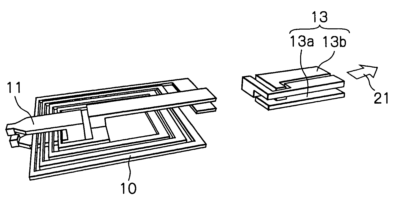
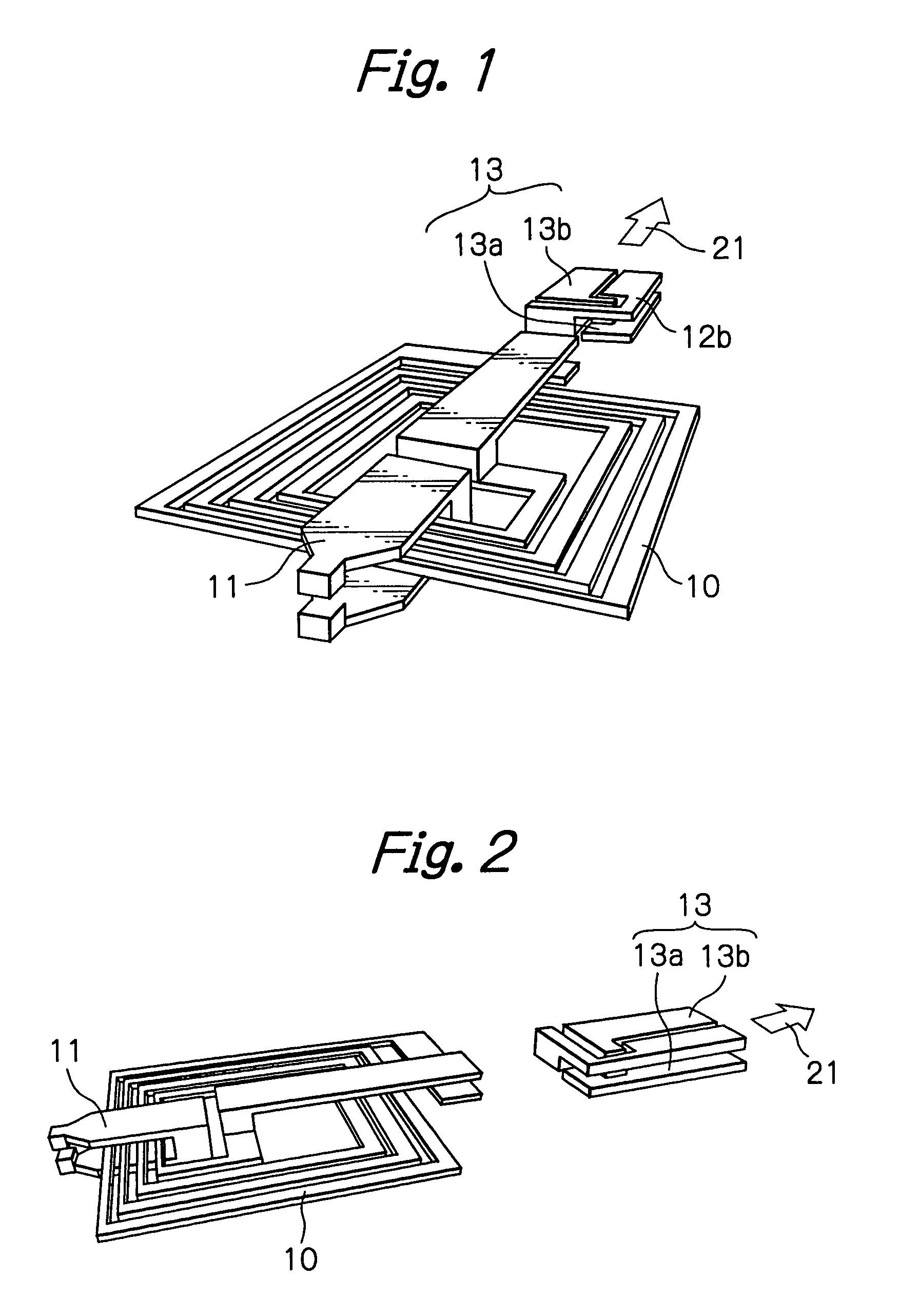
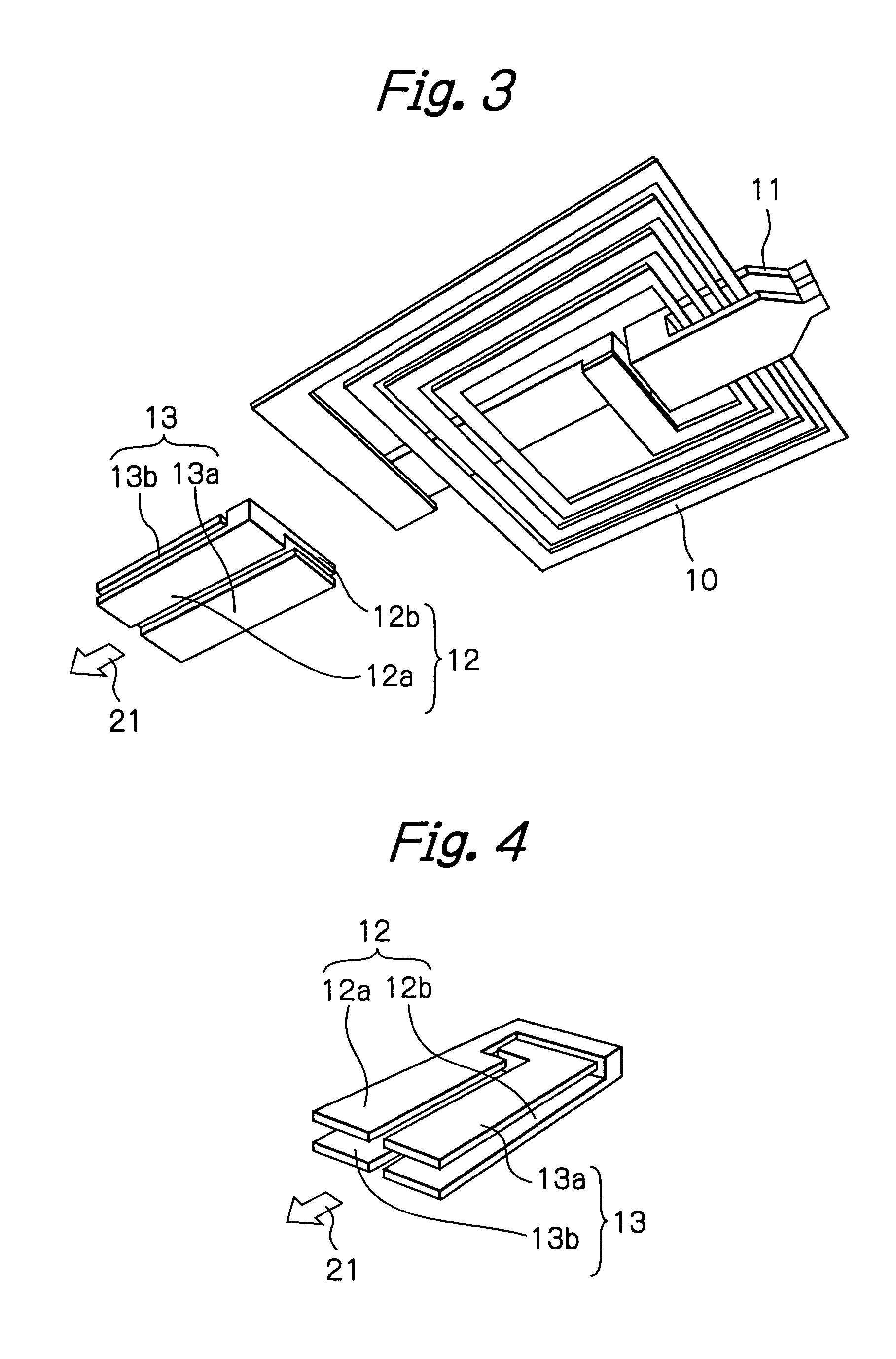
[0032]FIG. 1 illustrates a simple partial configuration of yoke layers, a coil conductor and trace conductors of a thin-film magnetic head as a preferred embodiment according to the present invention, FIG. 2 illustrates the partial configuration of the yoke layers, the coil conductor and the trace conductors of the thin-film magnetic head in this embodiment, seen from a different direction from FIG. 1, FIG. 3 illustrates the partial configuration of the yoke layers, the coil conductor and the trace conductors of the thin-film magnetic head in this embodiment, seen from a further different direction from FIG. 1, FIG. 4 illustrates a partial configuration of the trace conductors in this embodiment, seen from a different direction from FIG. 3, FIG. 5 illustrates another configuration of the trace conductors in FIG. 6 illustrates another configuration of the trace conductors in this embodiment, seen from a different direction from FIG. 5, FIG. 7 illustrates a top view of another configu...


PUM


Abstract

A thin-film magnetic head includes an insulation gap, a pair of yoke layers with one ends and the other ends, respectively, the one ends constituting magnetic poles separated with each other by the insulation gap, the other ends being magnetically coupled with each other, a coil conductor wound around at least one of the pair of yoke layers, first and second trace conductors with one ends electrically connected to both ends of the coil conductor, respectively, and first and second connection bumps electrically connected to the other ends of the first and second trace conductors, respectively. The first trace conductor includes a lower conductor layer and an upper conductor layer connected in parallel with each other, the second trace conductor including a lower conductor layer and an upper conductor layer connected in parallel with each other. The upper conductor layer of the first trace conductor and the lower conductor layer of the second trace conductor are arranged from top to bottom to face to each other. The upper conductor layer of the second trace conductor and the lower conductor layer of the first trace conductor are arranged from top to bottom to face to each other.

Description

FIELD OF THE INVENTION[0001]The present invention relates to a thin-film magnetic head element provided with an inductive write head element.DESCRIPTION OF THE RELATED ART[0002]Such a thin-film magnetic head has a yoke magnetically coupled with two magnetic poles separated from each other by a recording gap, a coil wound around the yoke, a pair of trace conductors electrically connected to the coil, and connection bumps electrically connected to the pair of trace conductors. Write operation of magnetic information is performed by flowing a write current through the coil via the connection bumps and the trace conductors.[0003]The write current applied to the coil is in general rectangular wave shape pulses. Wave shape and magnitude of current actually flowing through the coil when the rectangular wave shape pulses are applied vary depending upon structure of the thin-film magnetic head, upon an output impedance of a current source connected with the coil, and upon a frequency and a v...

Claims


Application Information

Patent Timeline
IPC IPC(8): G11B5/00G11B5/17G11B5/31
CPCG11B5/313G11B5/17G11B2005/0013
Inventor KASAJIMA, TAMONSHIRAISHI, MASASHI
Owner SAE MAGNETICS (HK) LTD
Learn More