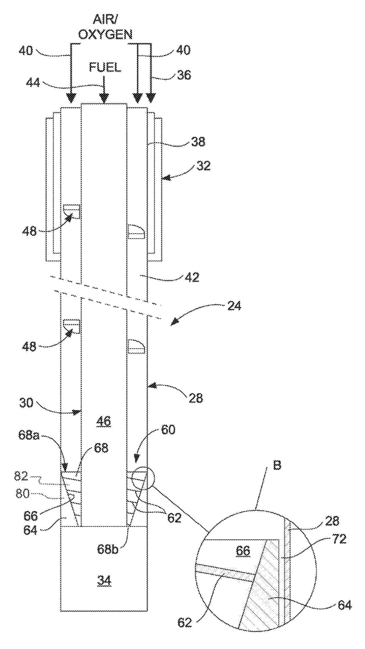
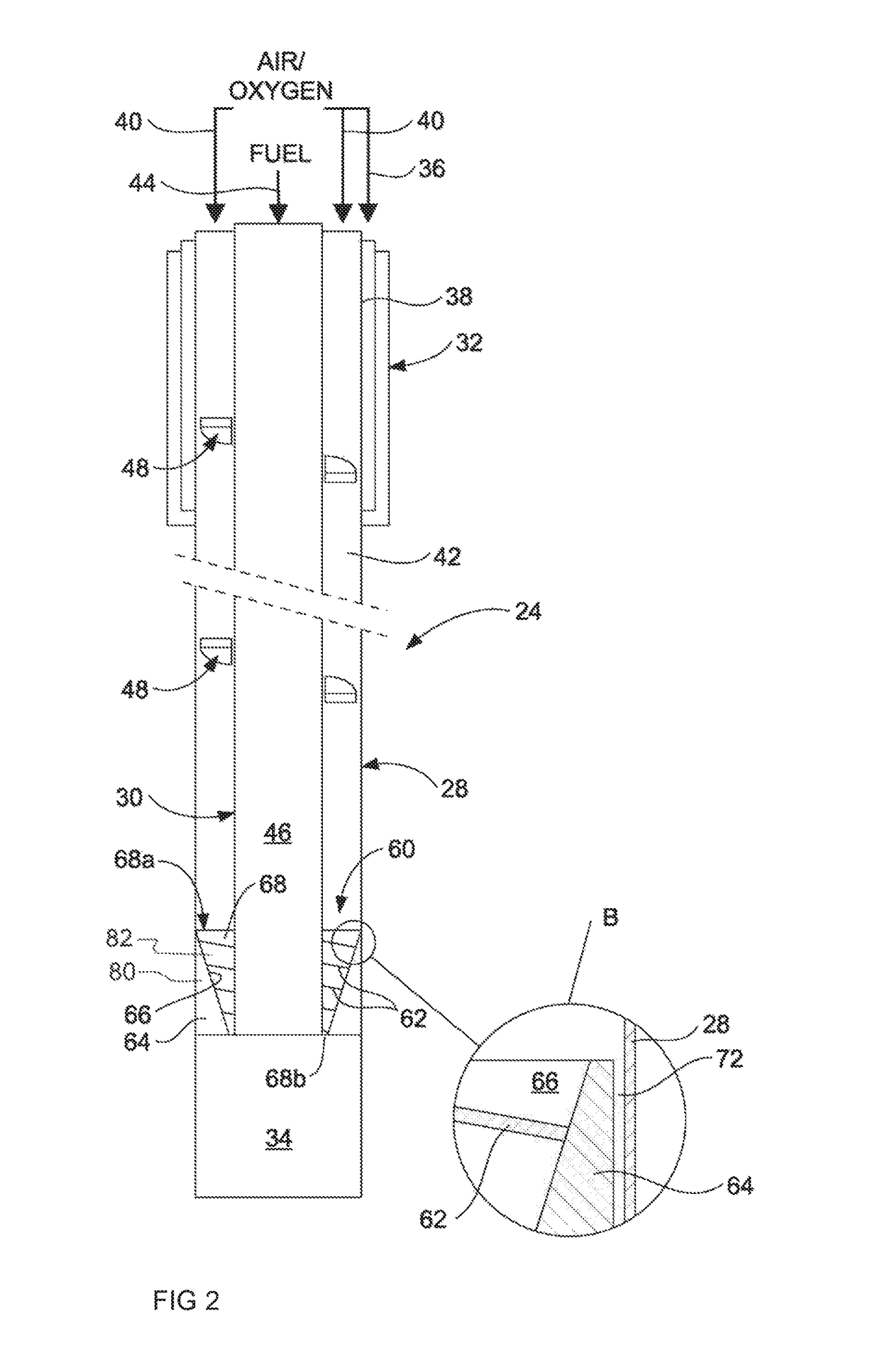
[0033]The present invention provides a lance for top submerged lancing (TSL) injection in a pyro-metallurgical operation. The lance has at least two substantially concentric pipes, with an annular passage for oxygen-containing gas defined between an outermost one of the pipes and a next adjacent pipe and a further passage for fuel defined within an innermost one of the pipes. The outermost pipe has a lower part of its length, from a submergible lower outlet end of the lance, by which the outermost pipe extends beyond an outlet end of the or each other pipe to define between the outlet end of the outermost pipe and the outlet end of the or each other pipe a chamber with which the passage for oxygen-containing gas communicates. The lance further includes a gas flow-modifying device that is disposed in a lower end section of the passage for oxygen-containing gas, adjacent to the chamber, and that is operable to impart an inward flow component, away from the inner surface of the outermost pipe, to oxygen-containing gas passing into and longitudinally within the chamber towards the outlet end of the lance and thereby enhance mixing of the oxygen-containing gas with fuel passing into the chamber from the passage for fuel. The flow-modifying device has at least one inner component of helical form, and an outer component that extends around the at least one inner component, such that the flow-modifying device constrains gas flowing through to the lower end section of the annular passage to a helical flow path, of decreasing cross-section, around the outer surface of the next adjacent pipe.
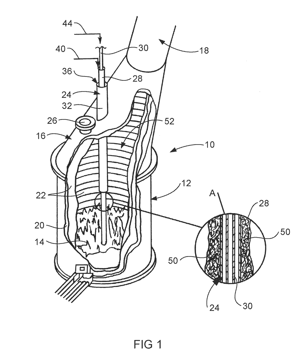
[0035]As will be appreciated from earlier description on the Background to the Invention, the lance initially is suspended over a slag bath so the flame generated from the combustible mixture impinges on the slag surface to cause an external lower end section of the lance to be coated by splashed slag droplets. The slag is solidified by the cooling effect of the flow of oxygen-containing gas along and beyond the annular passage for oxygen-containing gas, to form a solidified slag coating that is able to be maintained even after the lance is lowered to submerge the lower end of the lance within the slag to enable the flame to generate a combustion zone within the slag. This procedure has been used widely in numerous different pyro-metallurgical processes, although difficulties are encountered in some operations. For example, mixing of the oxygen-containing gas and the fuel may not be sufficient to achieve efficient combustion of the fuel, resulting in difficulty in maintaining the bath temperature by the submerged combustion and dispersal of fuel within the bath in which the fuel acts, contrary to intentions, as a reducing agent. Also, particularly at bath temperatures close to the upper end of the temperature range for use in TSL technology, the required solid slag coating can be difficult to maintain and, where that coating is lost, rapid erosion of the outermost pipe occurs. At such higher temperatures, the cooling effect provided by the oxygen-containing gas can be inadequate for cooling the outermost pipe, while the combustion flame can pass too close to the inner surface of the outermost pipe and further exacerbate the difficulty in adequately cooling the outermost pipe. The flow-modifying device of the lance according to the present invention enables improved operation by facilitating mixing of the oxygen-containing gas and thereby improving the efficiency of fuel combustion, as well as acting to concentrate the combustion flame and thereby increasing the spacing of the flame from the inner surface of the outermost pipe and so assisting in maintaining the solidified slag coating.
[0036]The lance of the invention preferably includes at least one single- or multi-start helical vane swirler in the annular passage for oxygen-containing gas. U.S. Pat. No. 4,251,271 to Floyd proposes use of a lance with only one swirler for oxygen containing gas extending over a major part of the length of the annular passage. However, the lance of the present invention preferably includes at least one relatively short swirler, with there more preferably being two or more such shorter swirlers which, in their preferred multi-start form, also are referred to as sets. This is in line with current practices as the use of short swirlers or sets, rather than longer swirlers as in U.S. Pat. No. 4,251,271, results in a lower gas pressure drop between the upper and lower ends of the lance, so enabling use of a lower gas supply pressure.
[0037]The swirlers cause spinning of the oxygen containing gas injected along the annular passage. As a result the gas is forced centrifugally against the inner surface of the outermost pipe, enhancing the cooling effect provided by the gas relative to the cooling achievable without swirlers. However, this action of the swirlers is the opposite of that required for good mixing of the gas with fuel in the chamber. That is, the gas is required to move inwardly, rather than outwardly, in order to obtain efficient mixing in the chamber, and the flow-modifying device of the invention is to offset any disadvantage resulting from the action of the swirlers.
[0038]The flow-modifying device can take a variety of forms. However, in each form, the device functions by imparting to the gas flowing longitudinally towards the chamber through the lower end section of the annular passage for oxygen-containing gas, a flow component away from the inner surface of the outermost pipe. The component may in effect be somewhat radial or radial and longitudinal but, in any event, preferably generates substantial turbulence or eddy currents in the oxygen-containing gas flowing into and within the chamber so that mixing of the gas and fuel is further enhanced.
[0043]The present invention provides a lance for top submerged injection that, due to the enhancement of gas flow into and through the mixing chamber defined in the lower part of the length outer pipe, provides improved mixing of the gas with fuel being injected, improved combustion of the mixture, and a stronger combustion flame that is concentrated away from the inner surface of the outer pipe. Also, the enhancements enable the protective layer of solidified slag to be better maintained, even at higher operating temperatures, or to be maintained over a longer operating period at a given temperature, providing a reduction in the operating cost for the pyro-metallurgical operation in which the lance is used by increasing the operating time between successive shut downs for lance replacement.
