Shielding cage assembly adapted for dense transceiver modules

a technology of shielding cage and transceiver module, which is applied in the direction of electrical apparatus construction details, localised screening, instruments, etc., can solve the problems that the structure cannot meet the requirement of stackable mounting of transceiver modules in interface communication equipment, and the prior art shielded transceiver modules are too difficult to assemble densely to a circuit board, etc., and achieve good air ventilation

Active Publication Date: 2005-12-06
GOOGLE LLC
View PDF5 Cites 36 Cited by
  • Summary
  • Abstract
  • Description
  • Claims
  • Application Information

AI Technical Summary

Benefits of technology

[0007]An object of the present invention is to provide a shielding cage assembly for receiving a plurality of transceiver modules therein while allowing good air ventilation.

Problems solved by technology

Prior art shielded transceiver modules are too difficult to assemble densely to a circuit board.
However, this kind of structure cannot satisfy the requirement to stackably mount transceiver modules in interface communication equipment.

Method used


Image

  • Shielding cage assembly adapted for dense transceiver modules
  • Shielding cage assembly adapted for dense transceiver modules
  • Shielding cage assembly adapted for dense transceiver modules

Examples


Embodiment Construction

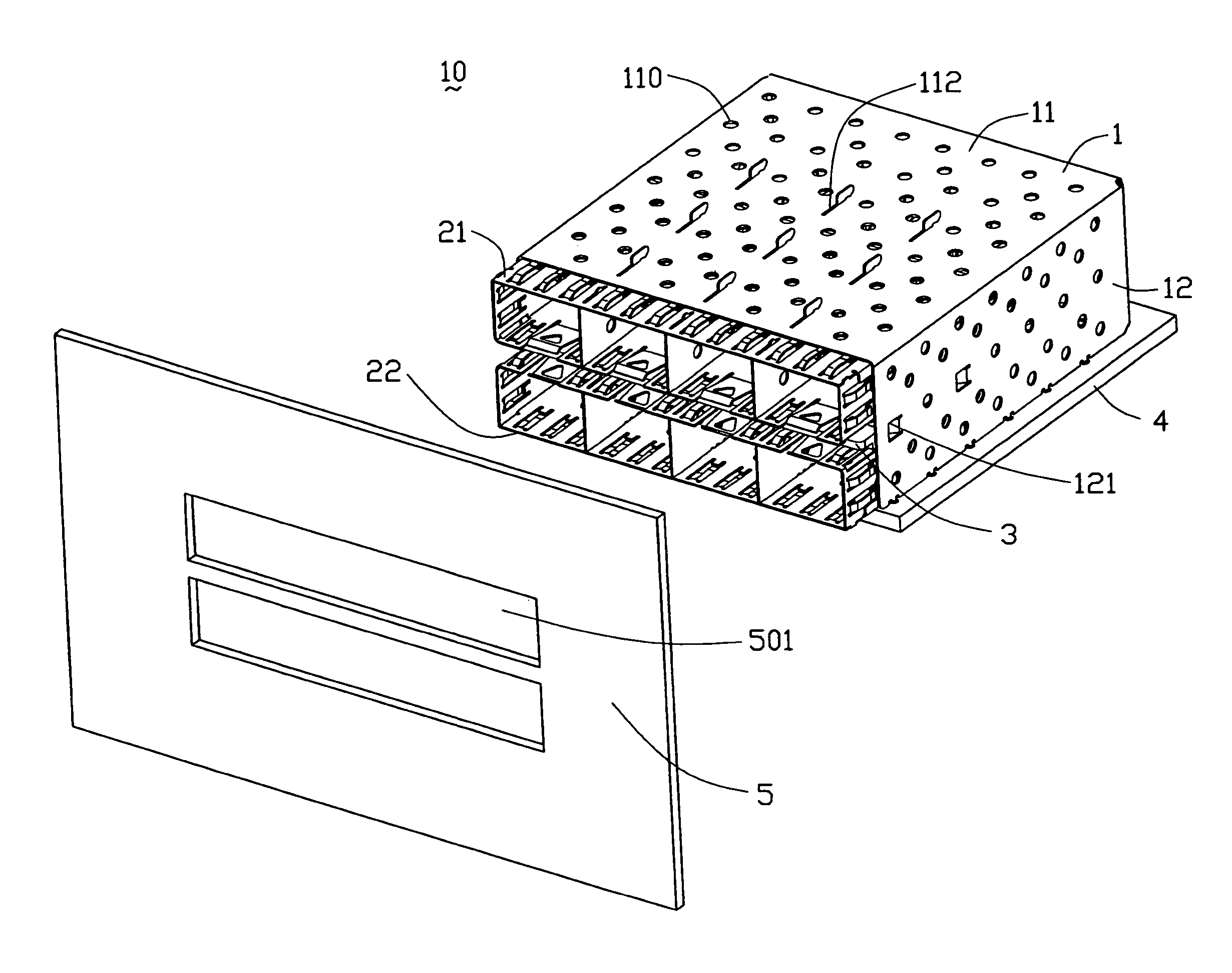
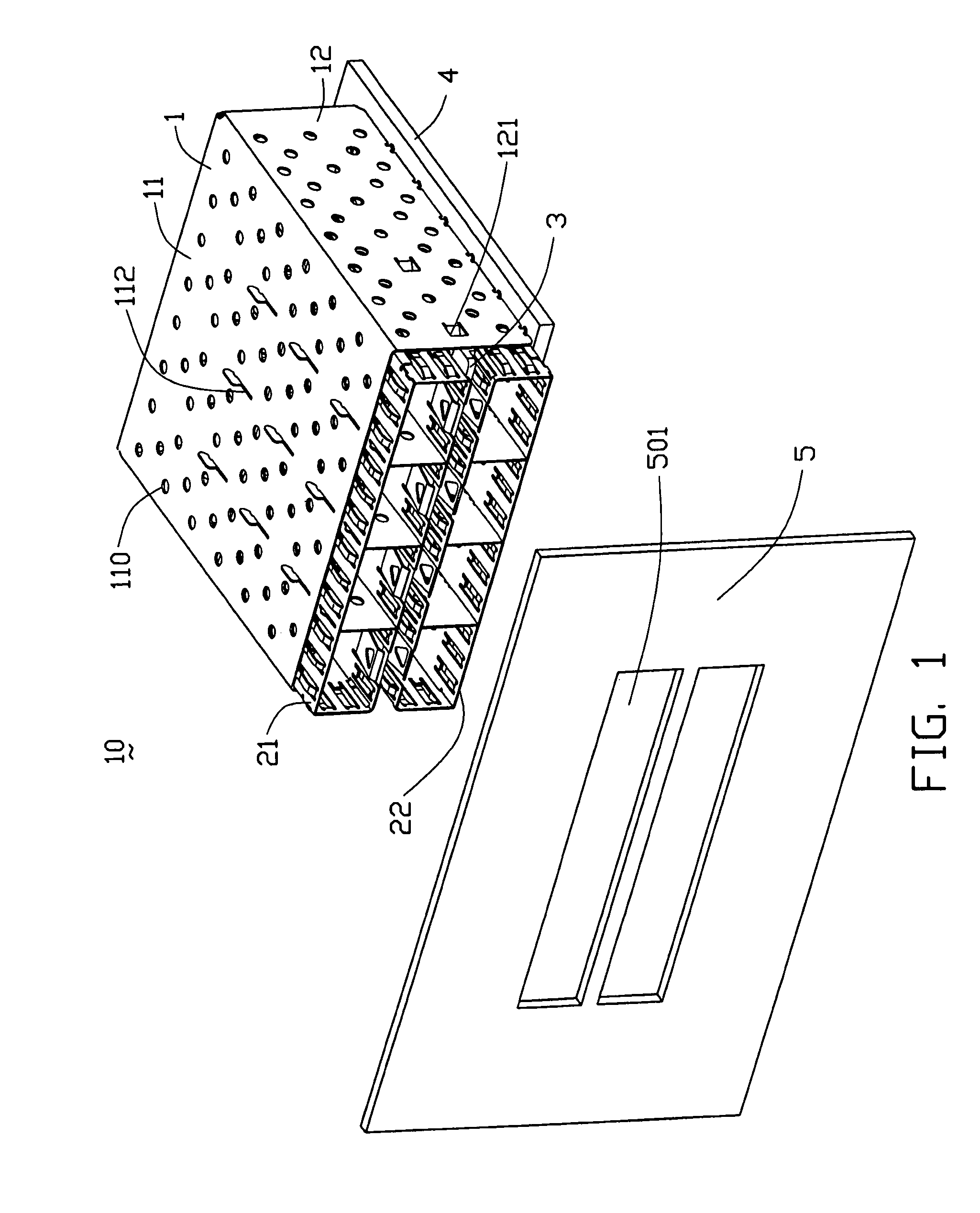
[0016]Referring also to FIG. 1, a shielding cage assembly 10 in accordance with the present invention includes a metal hanger 1, an upper shielding cage 21, a lower shielding cage 22 and a spacer 3. The hanger 1 covers the upper and lower shielding cages 21, 22 and the spacer 3.

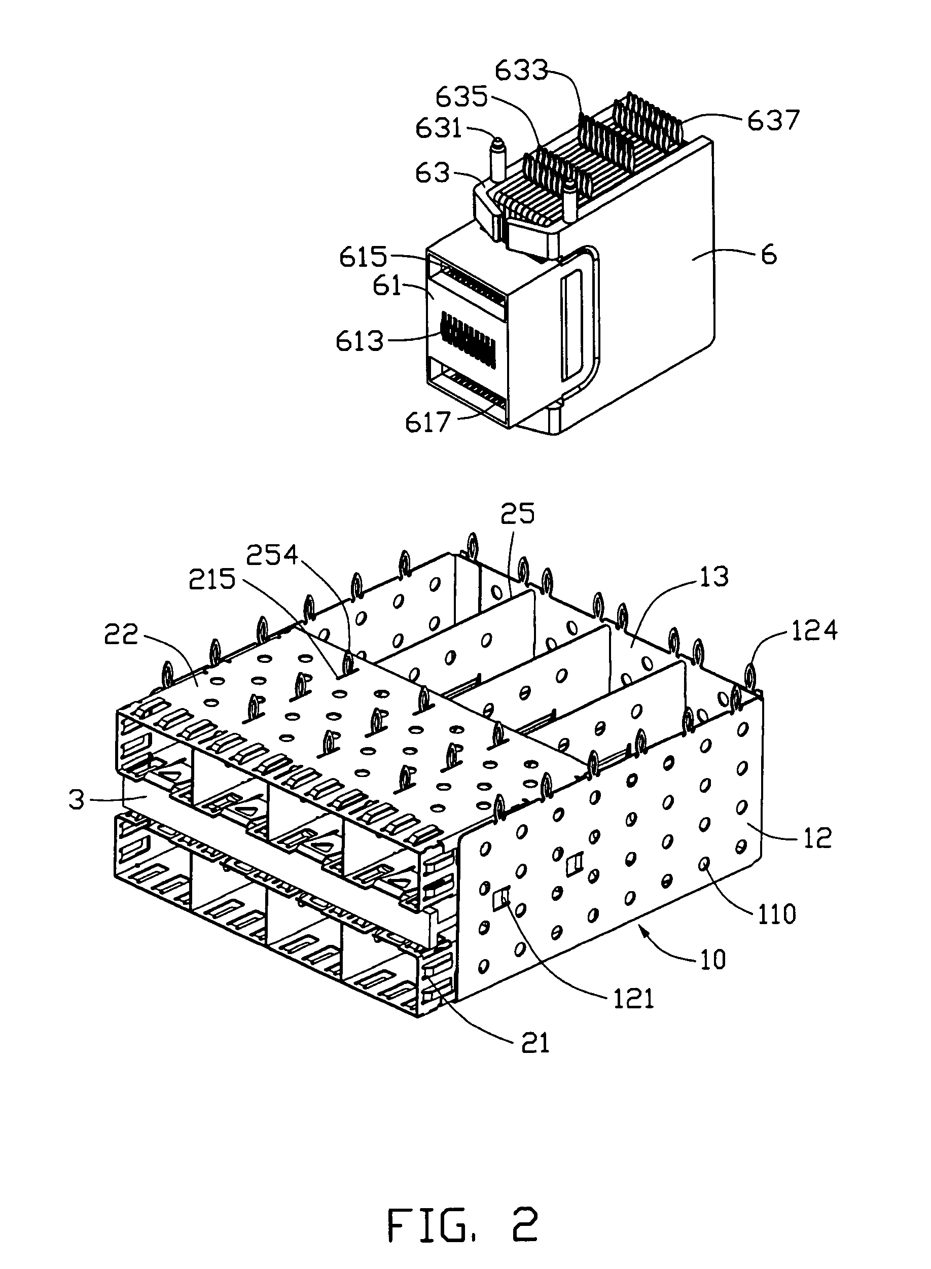
[0017]Referring also to FIG. 2, the hanger 1 is formed from a single sheet of metal and is pressed into a rectangular receptacle box, which includes a top wall 11, two side walls 12 extending downwardly therefrom, and a rear wall 13 extending between the two side walls 12. An opening (not labeled) is formed by the top and side walls 11, 12, which opening has a rearward boundary at the rear wall 13. A plurality of mounting pins 124 with needle-eyes therethrough respectively extends downwardly from the side and rear walls 12, 13. A plurality of slits 112 is defined through the top wall 11, arranged in parallel lines in a frontward to rearward direction. A pair of inward tabs 121 extends from each side wall 12 t...


PUM


Abstract

A transceiver module assembly includes a printed circuit board (4), a plurality of transceiver modules, a plurality of electrical connectors (6) adapted to connect between the plurality of transceiver modules and the printed circuit board, and a shielding cage assembly (10) which is mounted to the printed circuit board for receiving the transceiver modules and the electrical connectors therein. The shielding cage assembly includes at least one shielding cage (21, 22), a spacer (3), and a hanger (1). The at least one shielding cage and the spacer are mechanically retained in the hanger, and the spacer mechanically engages with the shielding cage for good air ventilation.

Description

BACKGROUND OF THE INVENTION[0001]1. Field of the Invention[0002]This invention relates generally to a cage for shielding components from electromagnetic interference, and more particularly to a shielding cage assembly for arranging a plurality of transceiver modules therein. A copending application filed Jun. 6, 2003 and tided “2×4 SHIELDING CAGE ASSEMBLY ADAPTED FOR MULTIPLE TRANSCEIVER MODULES” and having the same applicant and the same assignee with as the instant application, and a contemporaneously filed application having the same title, the same applicant and the same assignee as the instant application, are both referred hereto.[0003]2. Description of the Related Art[0004]A transceiver module is a discrete unit used in interface communication equipment, and is normally singly received in a cage that provides shielding against electromagnetic interference (EMI). Prior art shielded transceiver modules are too difficult to assemble densely to a circuit board. Therefore, an inex...

Claims


Application Information

Patent Timeline
Patent Type & Authority Patents(United States)
IPC IPC(8): H04B1/38H05K9/00
CPCG02B6/4277H05K9/002H05K9/0058G02B6/4246
Inventor HWANG, JENG-YIH
Owner GOOGLE LLC
Why Eureka
Try Eureka