Watermarking with separate application of the grid and payload signals

a payload signal and watermarking technology, applied in the field of printing, can solve the problems of time-consuming and laborious process of applying the changes specified by the watermark tile, and the general uniformity of the signal of the payload, so as to avoid creating significant visual artifacts and less effor

Inactive Publication Date: 2005-12-06
DIGIMARC CORP
View PDF49 Cites 19 Cited by
  • Summary
  • Abstract
  • Description
  • Claims
  • Application Information

AI Technical Summary

Benefits of technology

[0007]The present invention separately applies the watermark grid signal and the watermark payload signal to an image. The process of the present invention is particularly useful in situations where variable data such as serial numbers (or other image specific data) is being embedded in a series of images. In such situations the grid signal can be uniform over an entire sequence of images and only the payload signal need be changed before being printed on each image. With the present invention time, computational and labor intensive processes can be applied to the task of embedding the grid signal in the image to insure that visual artifacts...

Problems solved by technology

The process of applying the changes specified by a watermark tile is a complicated process.
The techniques used to insure that visual artifacts are not created can be a time, com...

Method used


Image

  • Watermarking with separate application of the grid and payload signals
  • Watermarking with separate application of the grid and payload signals
  • Watermarking with separate application of the grid and payload signals

Examples


Embodiment Construction

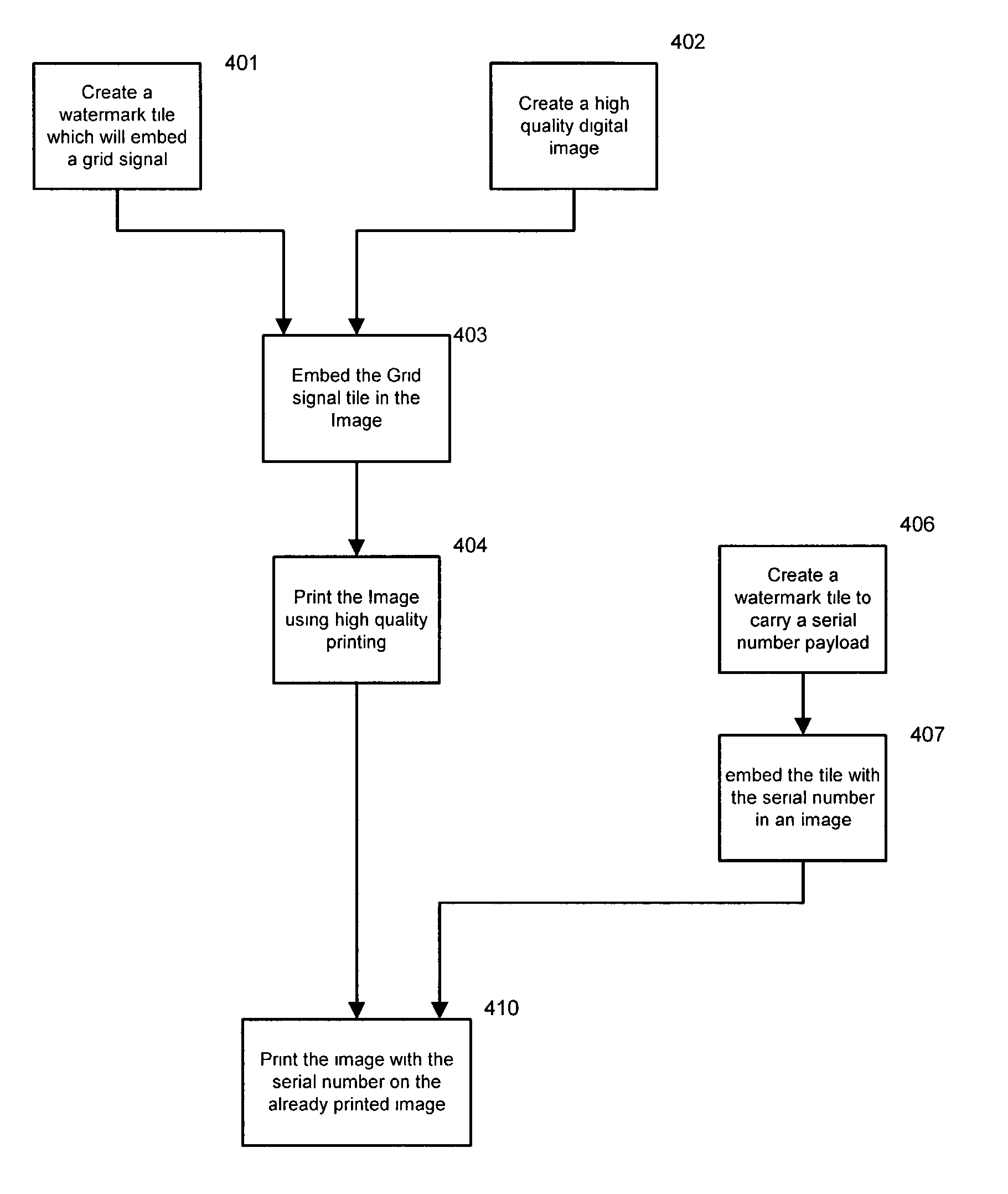
[0012]Two embodiments of the invention will be described. The first embodiment involves applying serial numbers to high quality printed documents such as paper currency. The second embodiment involves applying variable watermark data to documents which are printed at very high speed such as product containers or merchandise coupons. Various alternatives are also described.

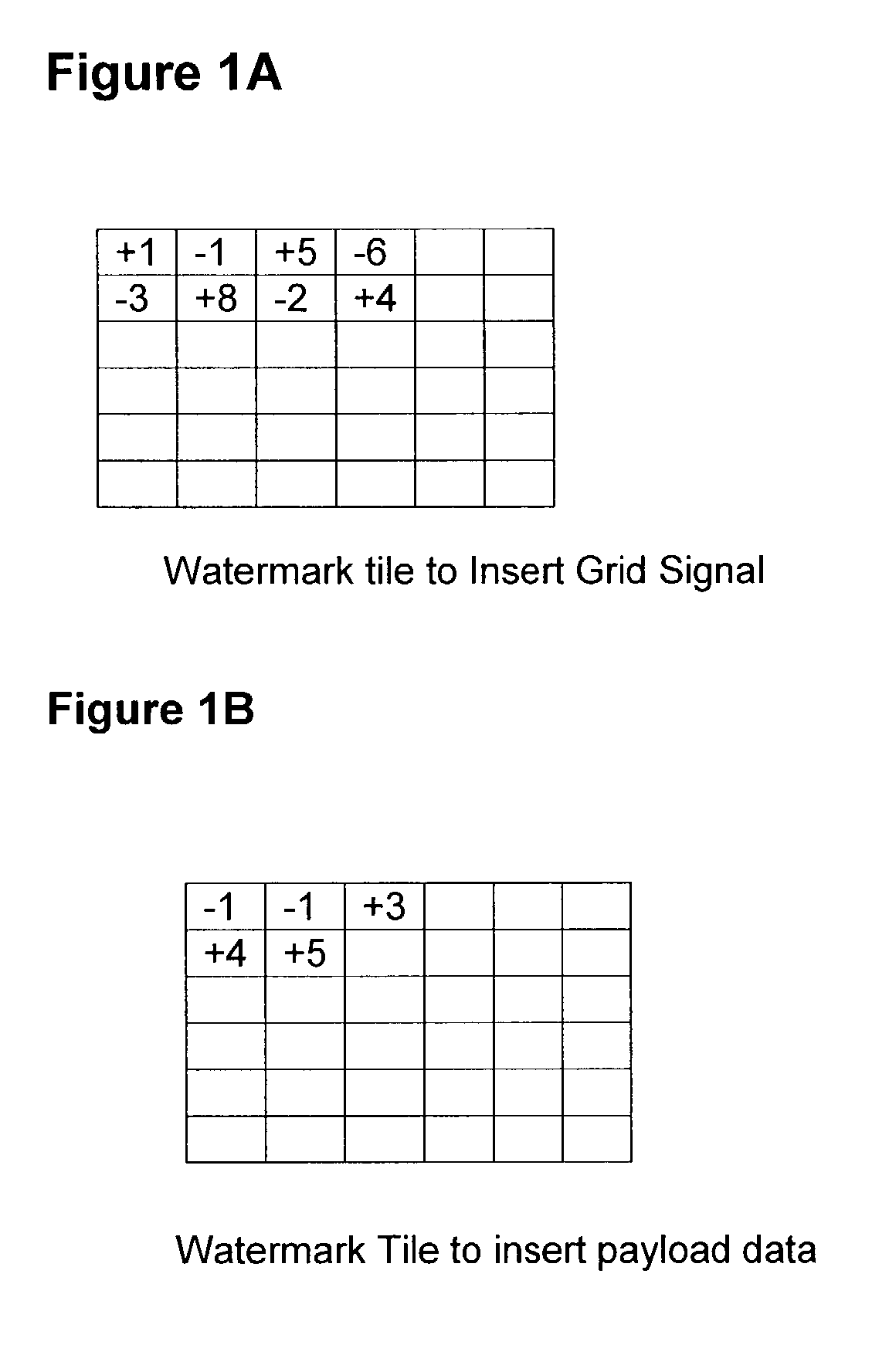
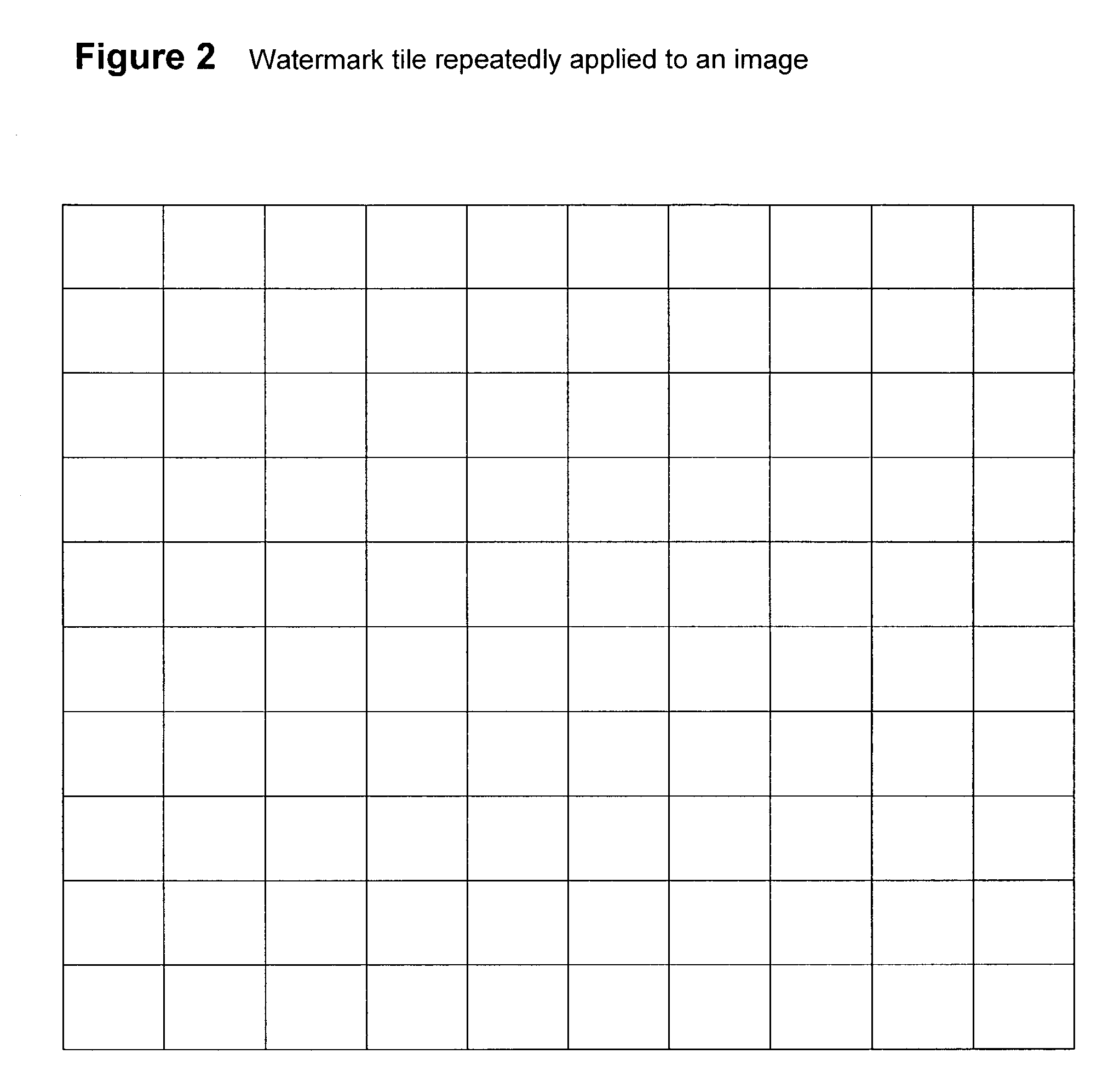
[0013]Each of the embodiments use a first watermark tile to specify the changes in an area of an image needed to embed a particular grid signal into the image. A second watermark tile is used to specify the changes in an area of an image needed to embed particular payload data into an image. FIG. 1 illustrates two watermark tiles. As is conventional with digital watermarks, the changes specified by the watermark tiles are embedded in multiple areas in an image. FIG. 2 illustrates a watermark tile embedded in an image 1000 times. The figure shows the multiple areas where the tile would be embedded in the image.

[0014...


PUM


Abstract

The watermark grid signal and the watermark payload signal are separately applied to an image. The process is particularly useful in situations where variable data such as serial numbers (or other image specific data) is being embedded in a series of images. In such situations the grid signal can be uniform over an entire sequence of images and only the payload signal need be changed before being printed on each image. The time, computational and labor intensive processes can be applied to the task of embedding the grid signal in the image to insure that visual artifacts are not created. After the image has been changed to embed the grid signal, the payload data can be inserted into at least a selected part of the image. Since the payload signal is less likely to create visual artifacts than the uniform grid signal, less effort need be used to avoid creating visual artifacts due to the payload signal. The relatively random nature of the payload data can be relied upon to avoid creating significant visual artifacts. The same bifurcated process can be used to apply digital watermarks to other media such as sound recordings where potential artifacts are in the nature of sound anomalies rather that visual artifacts.

Description

RELATED APPLICATIONS[0001]The present application is a continuation in part of application Ser. No. 09 / 694,465 filed Oct. 23, 2000 (now U.S. Pat. No. 6,763,122), which is a non-provisional application of provisional application 60 / 163,676 filed Nov. 5, 1999. The content of the above application and U.S. Patent is hereby incorporated herein.FIELD OF THE INVENTION[0002]The present invention relates to printing and more particularly to printing watermarked images.BACKGROUND OF THE INVENTION[0003]The technology for applying digital watermarks to images and for detecting and reading digital watermarks that are embedded in images is well developed. For, examples see issued U.S. Pat. Nos. 6,332,031, 5,721,788, 5,745,604 5,748,783 and 5,768,426. Also see the references cited in the above listed patents. There is a wide variety of literature that describes various digital watermarking techniques.[0004]Many digital watermarks include a grid signal and a payload signal. When a watermark is det...

Claims


Application Information

Patent Timeline
IPC IPC(8): G06T1/00H04N1/32
CPCG06T1/0028G06T1/005H04N1/32144H04N1/32304H04N1/32309H04N1/32352G06T2201/0065H04N2201/3233H04N2201/327G06F18/00
Inventor MILLER, MARC
Owner DIGIMARC CORP
Why Eureka
Try Eureka