Device for dispensing a liquid active substance

a technology for liquid active substances and devices, applied in liquid bottling, packaging goods, packaging under special atmospheric conditions, etc., can solve the problem of insufficient quantity of active substances in the capillary channels, and achieve the effect of increasing reliability

Inactive Publication Date: 2005-12-20
SKOT CHEM PRODS
View PDF14 Cites 29 Cited by
  • Summary
  • Abstract
  • Description
  • Claims
  • Application Information

AI Technical Summary

Benefits of technology

[0020]To prevent the liquid active substance from escaping from the distributor plate on the side located opposite the capillary channels, a wall is preferably integrally formed on the distributor plate. This wall partially engages over the carrying body laterally and, on three sides, forms a tray for the liquid active substance. This wall extends along the side which is located opposite the capillary channels and, in the toilet bowl, is directed towards the center. Moreover, this wall partially extends over the adjoining end sides, in order to form a termination at these locations. The wall could also be routed parallel to the capillary channels. A sealing groove is formed in the distributor plate on the inside of the wall and has a correspondingly shaped sealing lip of the carrying body engaging in it. This sealing lip, together with the sealing groove and the boundary wall, forms a labyrinth for the liquid active substance, with the result that the liquid cannot escape on the side of the device located opposite the capillary channels.
[0021]So that the liquid active substance no longer drips down from the sides of the distributor plate after flushing, it is of great advantage have a hollow with a siphon in the bottom of the plate, whose over-flow edge is below the capillary channels. The excess liquid it eh capillary channels only runs into the hollow after flushing. The siphon with its over-flow edge is positioned so far under the capillary channels and also below the end edge of the distributor plate, that the liquid running into the hollow only runs out via the siphon into the toilet bowl.
[0022]It is advantageous to form the hollow in the distributor plate as a groove which serves as the end running crossways at the open end of the capillary channels. The groove is only formed as a frontal end in front of the capillary channels. The groove shows a deep point where the low-position siphon is located. The groove is deep enough so that the siphon with its over-flow edge remains under the capillary channels, so that the liquid traces only run out through the siphon and do not drip down over the sides. Alternatively, the groove could span the capillary channels on three sides, which would increase reliability.
[0023]Furthermore, it is advantageous if the hollow in the distributor plate is formed as a shaft, which extends over several capillary channels and which is connected to a cross groove at the open end of the capillary channels. The hollow, formed as a shaft, is incorporated in the distributor plate and the result thereby is a smaller unit. As there are only little traces of liquid after flushing, a small shaft integrated in the capillary channels, in which the siphon is positioned, is sufficient.

Problems solved by technology

If the device is intended to act as an air freshener, then the quantities of active substance accommodated in the capillary channels are usually not sufficient.

Method used


Image

  • Device for dispensing a liquid active substance
  • Device for dispensing a liquid active substance
  • Device for dispensing a liquid active substance

Examples


Embodiment Construction

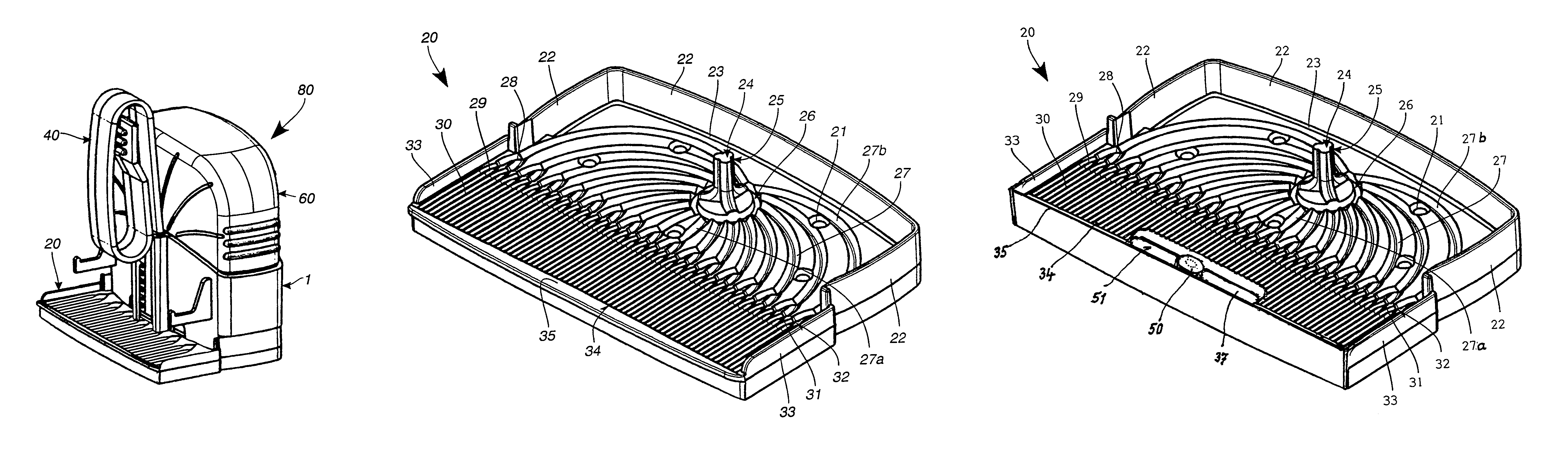
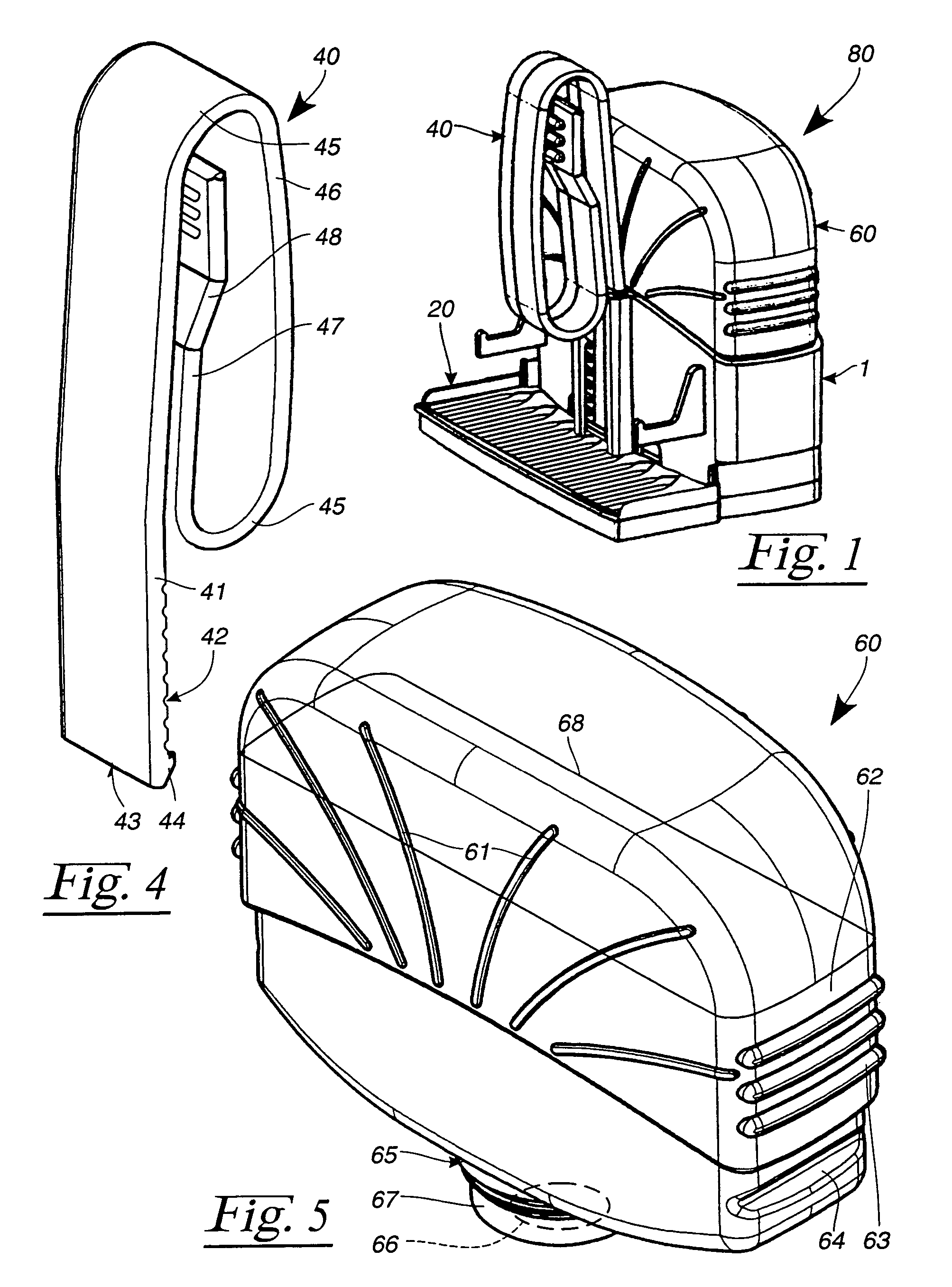
[0034]Referring now in detail to the drawings, FIG. 1 shows a device 80 for dispensing a liquid active substance. Device 80 comprises a carrying body 1, on the underside of which a distributor plate 20 is secured. A resilient clip 40 is provided on carrying body 1 and keeps device 80 on the rim of a toilet bowl (not illustrated). A supply container 60, which contains the liquid active substance, is plugged into carrying body 1. Device 80 is explained in more detail hereinbelow with reference to the illustrations shown in FIGS. 2 to 5.

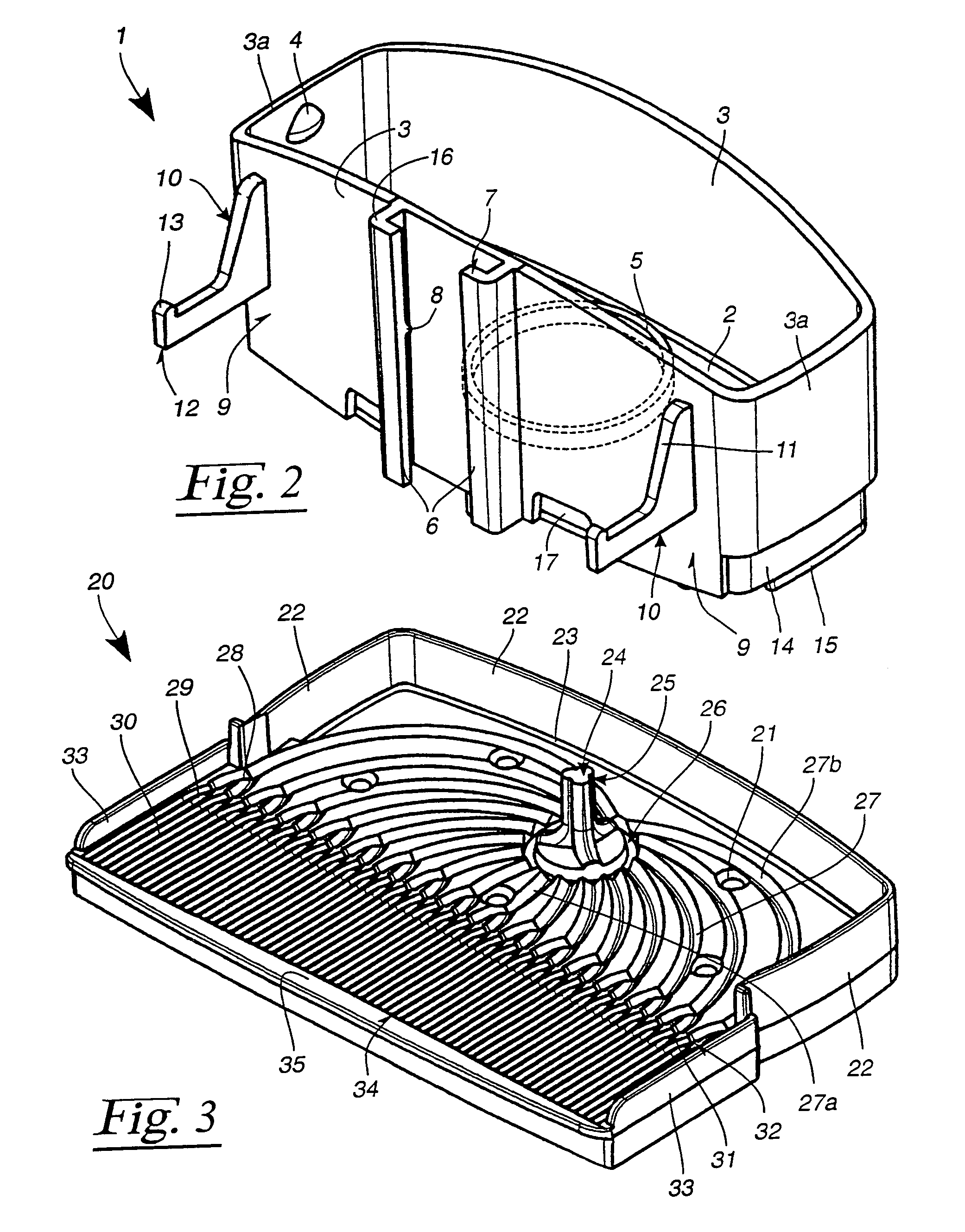
[0035]FIG. 2 shows carrying body 1 of device 80. This carrying body 1 has a base 2, from which four side walls 3, 3a extend upwards. Latching noses 4 are integrally formed on the inside of two mutually opposite end sides 3a of carrying body 1, and accommodate supply container 60 with arresting action. Integrally formed in base 2 is an inwardly oriented tubular mount 5 (illustrated by dashed lines), within which base 2 is interrupted.

[0036]In an upright ...


PUM

PropertyMeasurementUnit
opening angleaaaaaaaaaa

Abstract

A device for dispenses a liquid active substance into the flushing water of a toilet bowl. The device has a supply container provided with an opening on the underside and is filled with the liquid active substance. This supply container is retained in a carrying body which can be fixed on a rim of the toilet bowl. Retained on the underside of the carrying body is a distributor plate, which can be reached by the flushing water and has capillary channels. These capillary channels are connected to the opening of the supply container via distributor channels. The distributor channels here are branched and are each connected to a plurality of capillary channels.

Description

BACKGROUND OF THE INVENTION[0001]1. Field of the Invention[0002]The invention relates to a device for dispensing a liquid active substance into the flushing water of a toilet bowl.[0003]2. The Prior Art[0004]British Patent No. GB-A-2 345 494 discloses a device for dispensing a liquid active substance into a toilet bowl and has a distributor plate with capillary channels running through it. These capillary channels are connected to a spike-like extension which penetrates into an opening of a supply container for the liquid active substance. This achieves the situation where the capillary channels receive the liquid active substance until they have been filled. If the liquid active substance is flushed out of the distributor plate as a result of the toilet flushing, or if it partially evaporates, a corresponding quantity of liquid active substance runs in after it from the supply container. This prevents the liquid active substance from being dispensed in an uncontrolled manner from t...

Claims


Application Information

Patent Timeline
Patent Type & Authority Patents(United States)
IPC IPC(8): E03D9/03
CPCE03D9/032
Inventor KERAMIDAS, IOANNIS D.
Owner SKOT CHEM PRODS
Why Eureka
Try Eureka