Methods and apparatus for connecting tubulars using a top drive

a top drive and tubular technology, applied in the direction of manufacturing tools, drilling pipes, and well accessories, can solve the problems of inconvenient installation, inconvenient installation, and inconvenient use of the top drive,

Inactive Publication Date: 2005-12-20
WEATHERFORD TECH HLDG LLC
View PDF117 Cites 90 Cited by
  • Summary
  • Abstract
  • Description
  • Claims
  • Application Information

AI Technical Summary

Problems solved by technology

It has been observed that sections or stands of tubulars are often not as uniform as desired.
In particular, the sections or stands of tubulars are often not straight.
However, a section or stand of tubulars located in the spider would not always be in alignment with the top drive.

Method used


Image

  • Methods and apparatus for connecting tubulars using a top drive
  • Methods and apparatus for connecting tubulars using a top drive
  • Methods and apparatus for connecting tubulars using a top drive

Examples


Embodiment Construction

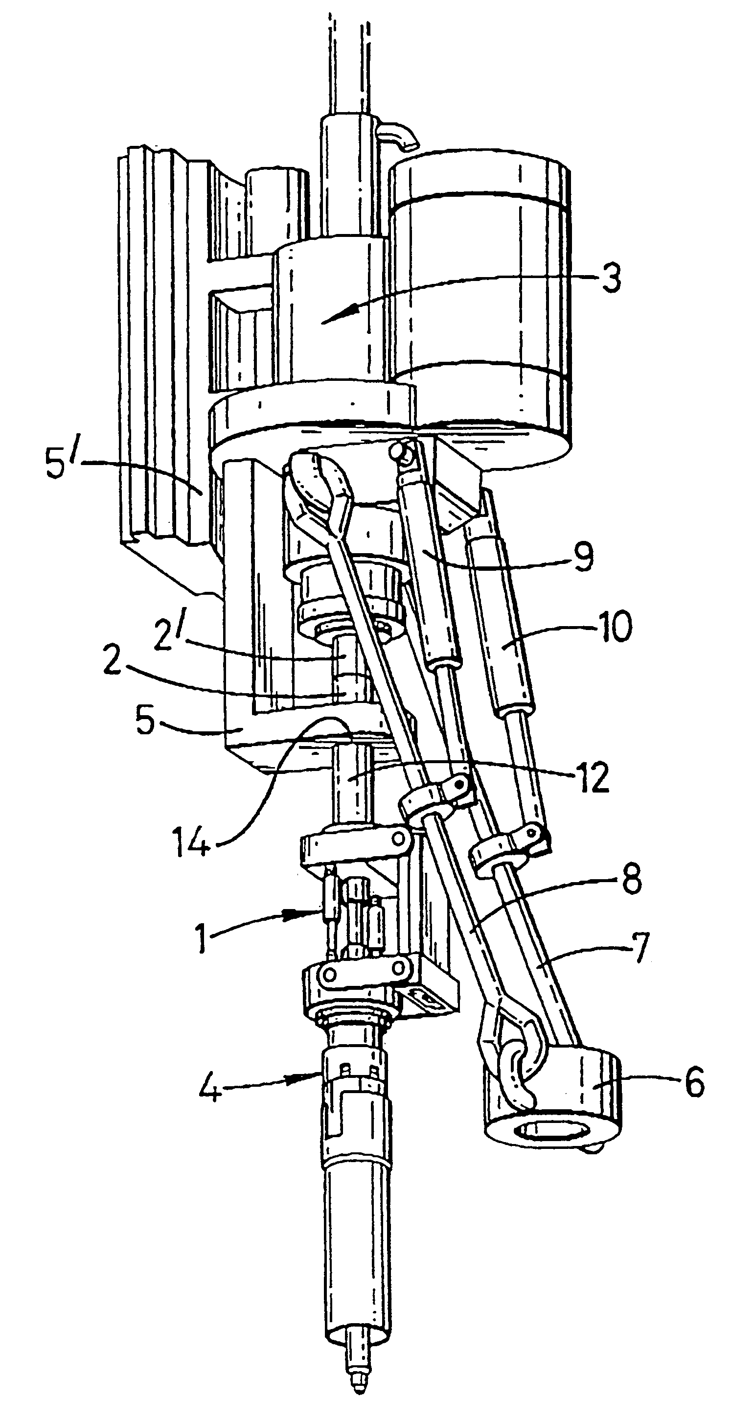
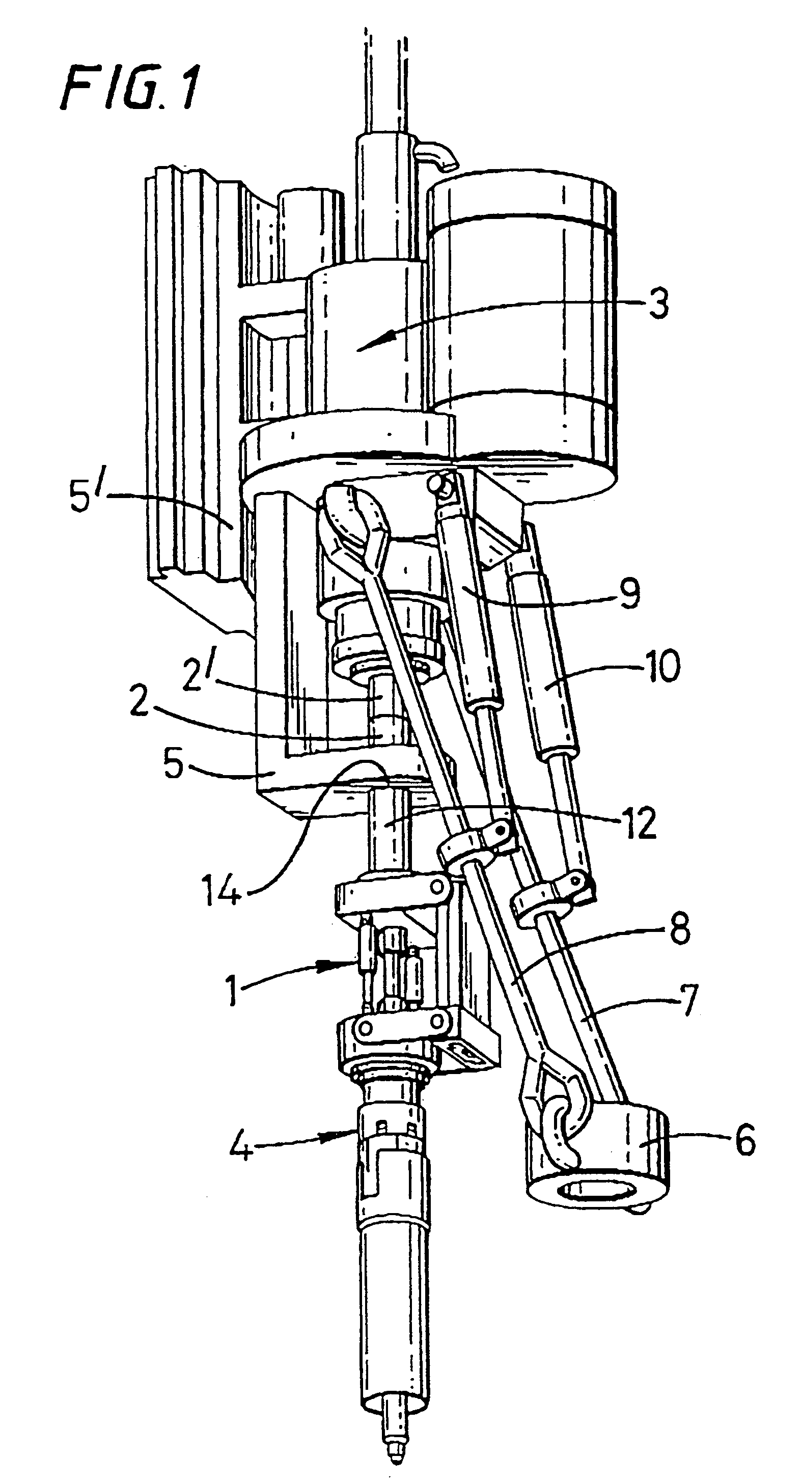
[0017]Referring to FIG. 1 there is shown an apparatus which is generally identified by reference numeral 1.

[0018]The apparatus I depends from a rotor 2′ of a top drive 3. A tool 4 for gripping a tubular depends from the lower end of the apparatus 1. A rigid guide member 5 is provided to guide the rotor 2 of the apparatus 1. The rigid guide member 5 is fast with a stator 5′ of the top drive 3. The rotor 2′ of the top drive 3 is coupled by a threaded connection to the rotor 2 of the apparatus 1. The rigid guide member 5 may be provided with a clamp for clamping the rotor 2 of the apparatus I so that the threaded connection to the rotor 2′ of the top drive 3 can be made, after which the clamp would be released.

[0019]An elevator 6 is provided on the end of bails 7, 8 which are hung from the top drive 3. Piston and cylinders 9, 10 are arranged between the bails 7, 8 and the top drive 3 for moving the elevator 6 from below the top drive 3 to an out of the way position.

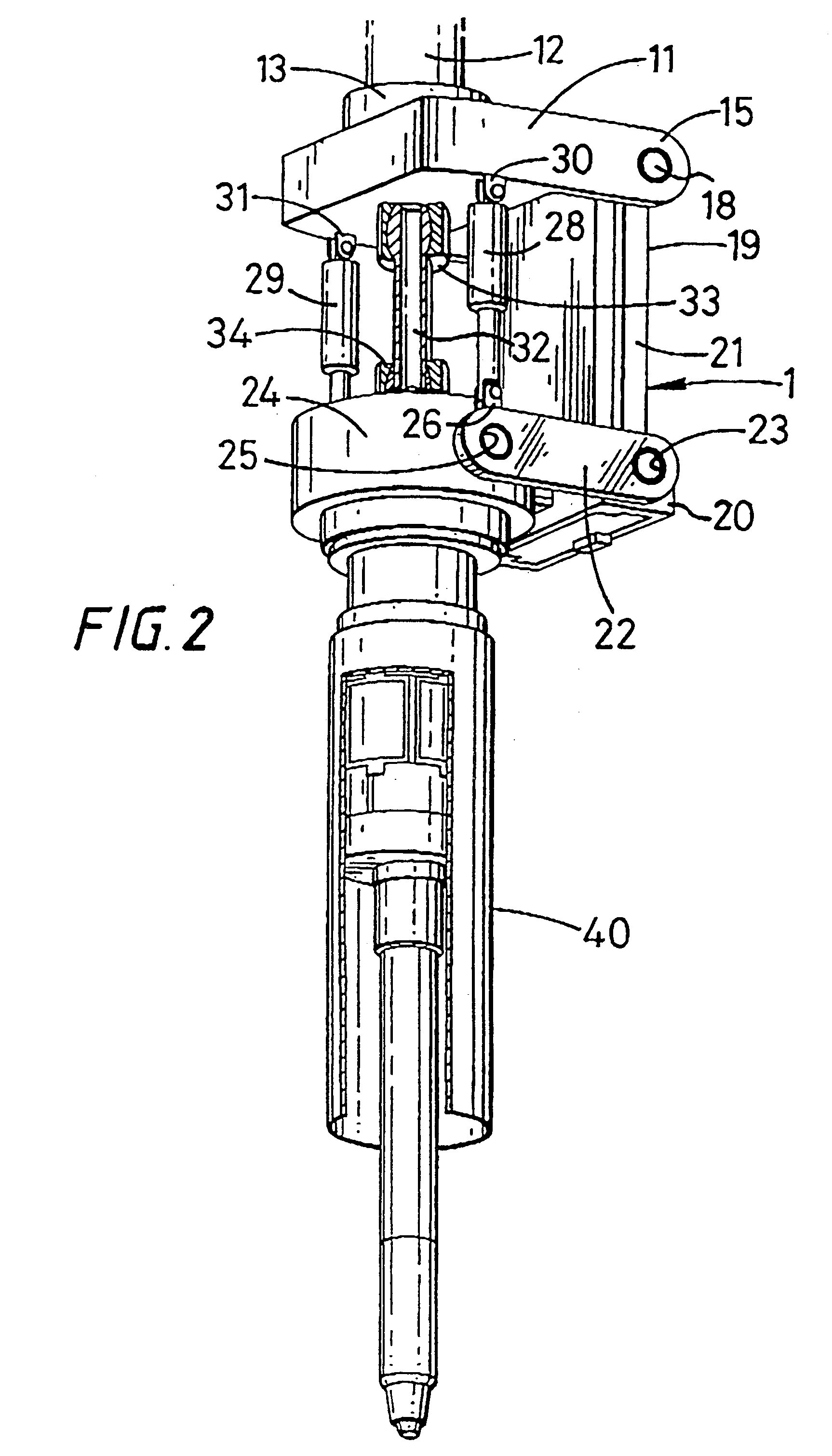
[0020]Referring now ...


PUM

PropertyMeasurementUnit
vertical movementaaaaaaaaaa
torqueaaaaaaaaaa
horizontal movementaaaaaaaaaa

Abstract

An apparatus for facilitating the connection of tubulars using a top drive, the apparatus comprising a stator attachable to said top drive, and a supporting member for supporting a tool, wherein means are provided to allow substantially horizontal movement of said supporting member.

Description

BACKGROUND OF THE INVENTION[0001]1. Field of the Invention[0002]This invention relates to methods and apparatus for facilitating the connection of tubulars using a top drive and is more particularly, but not exclusively for facilitating the connection of a section or stand of casing to a string of casing.[0003]2. Description of the Related Art[0004]In the construction of wells such as oil or gas wells, it is usually necessary to line predrilled holes with a string of tubulars known as casing. Because of the size of the casing required, sections or stands of say two sections of casing are connected to each other as they are lowered into the well from a platform. The first section or stand of casing is lowered into the well and is usually restrained from falling into the well by a spider located in the platform's floor. Subsequent sections or stands of casing are moved from a rack to the well centre above the spider. The threaded pin of the section or stand of casing to be connected i...

Claims


Application Information

Patent Timeline
Patent Type & Authority Patents(United States)
IPC IPC(8): E21B19/16
CPCE21B19/16Y10T29/49895Y10T29/49881Y10T29/49826Y10T29/53978Y10T29/49902
Inventor PIETRAS, BERND-GEORG
Owner WEATHERFORD TECH HLDG LLC
Why Eureka
Try Eureka