Selective one-way bit-driving apparatus

a one-way, drive-by technology, applied in the direction of wrenches, screwdrivers, manufacturing tools, etc., can solve the problem that the engagement shaft cannot transmit the torque it needs to be effective, and achieve the effect of reducing the number of cylinders

Active Publication Date: 2005-12-20
SHU ZU SHUNG
View PDF4 Cites 16 Cited by
  • Summary
  • Abstract
  • Description
  • Claims
  • Application Information

AI Technical Summary

Benefits of technology

[0005]It is another objective of the present invention to provide a reliable selective one-way bit-driving apparatus.

Problems solved by technology

Hence, this engagement cannot transmit adequate torque from the shaft 76 to the bit receiver 78.

Method used


Image

  • Selective one-way bit-driving apparatus
  • Selective one-way bit-driving apparatus
  • Selective one-way bit-driving apparatus

Examples


Embodiment Construction

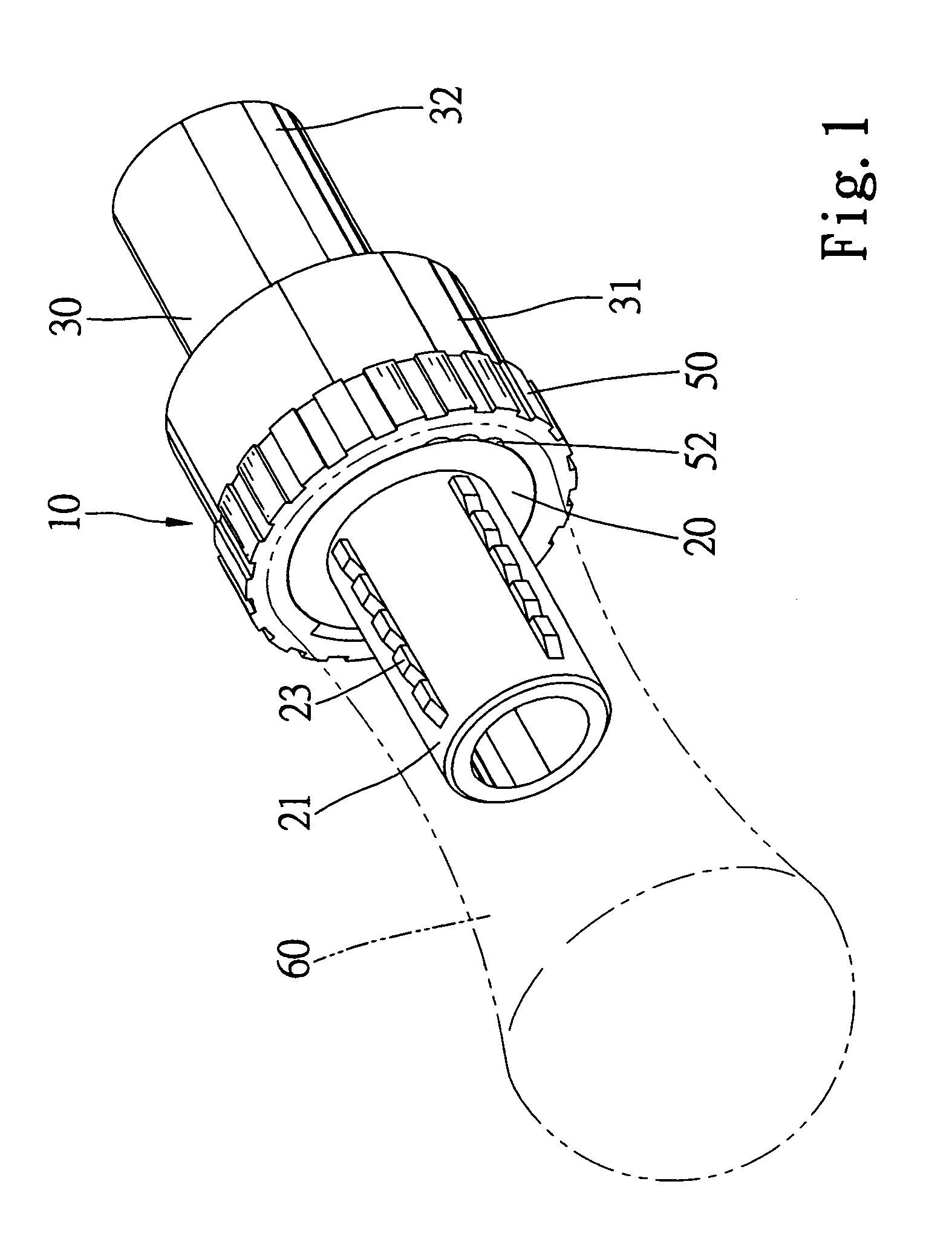
[0017]Referring to FIG. 1, according to a first embodiment of the present invention, a selective one-way bit-driving apparatus 10 is engaged with a handle 60 in order to drive a bit (not shown).

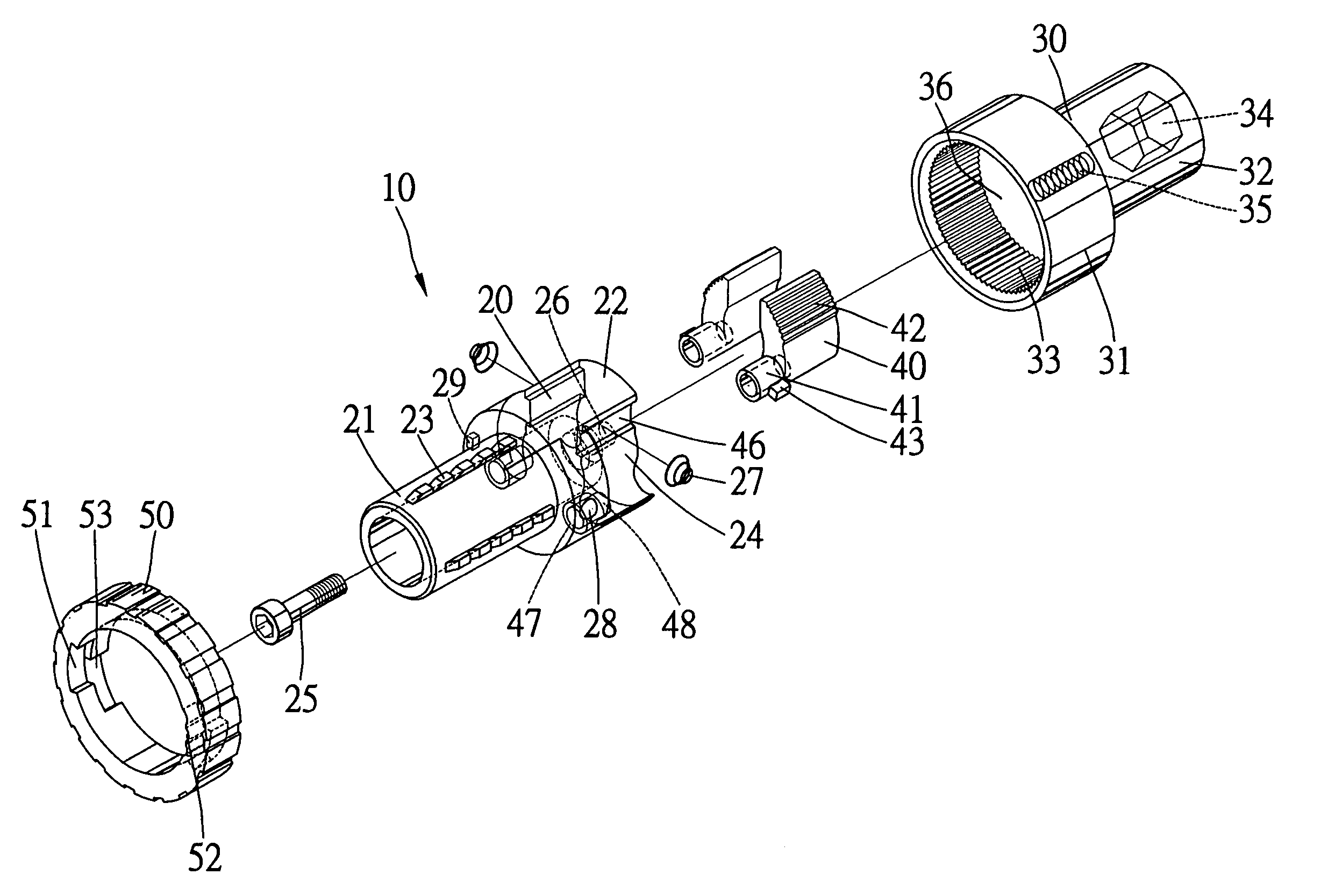
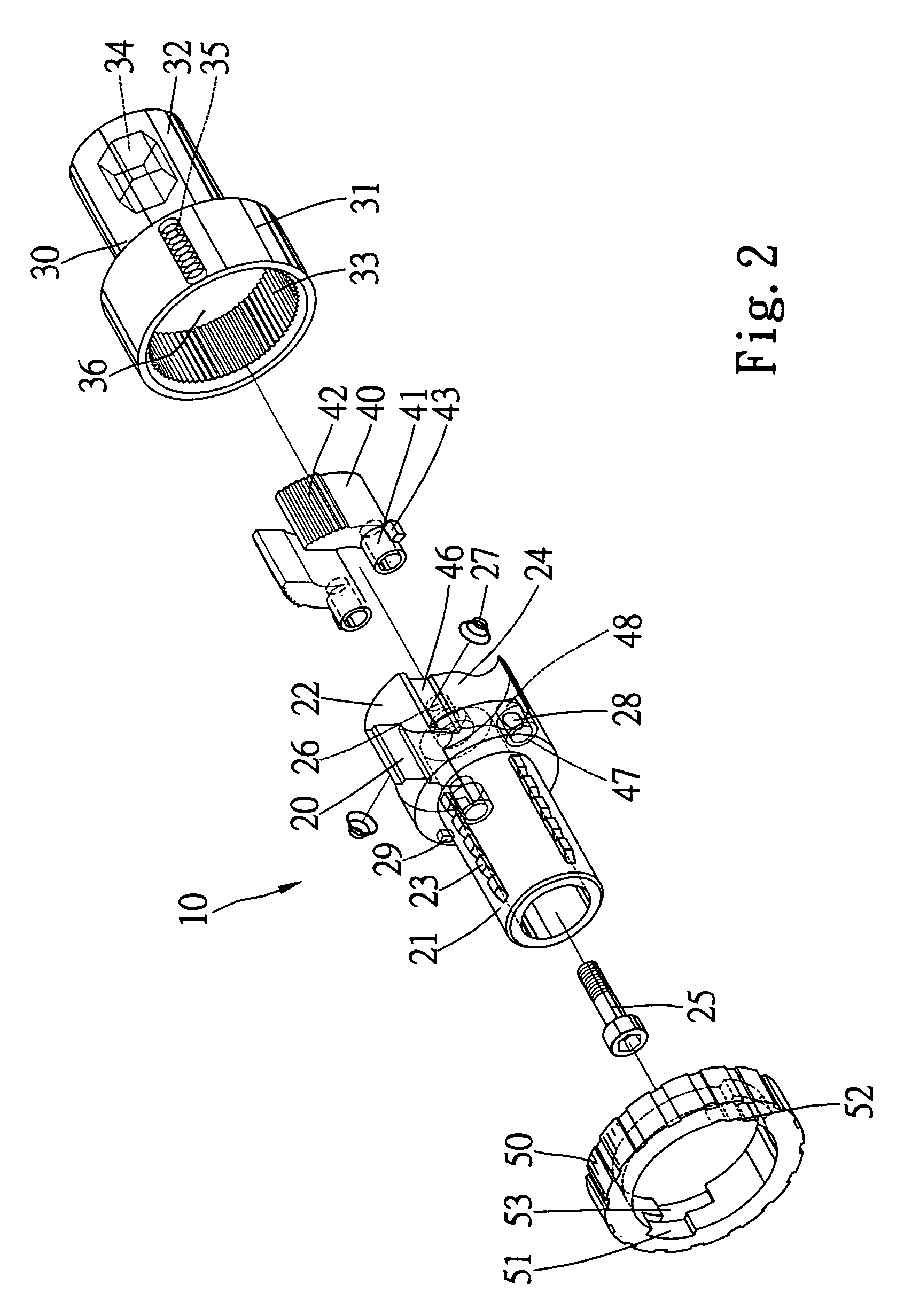
[0018]Referring to FIG. 2, the selective one-way bit-driving apparatus 10 includes a shaft 20 for connection with the handle 60, a bit receiver 30 for receiving the bit, two one-way drivers 40 each enabling the shaft 20 to drive the bit receiver 30 in only one direction and a switch 50 that can be manipulated so as to select one of the one-way drivers 40 for operation.

[0019]Referring to FIGS. 2 and 3, the shaft 20 defines an axial tunnel 26. The shaft 20 includes a first section 21 and a second section 22 with an external diameter greater than that of the first section 21. On the first section 21 are formed four rows of protrusions 23 for holding on to the handle 60 when the first section 21 is inserted in the handle 60. Two recesses 24 are defined in the periphery of the second section 22. T...


PUM


Abstract

A selective one-way bit-driving apparatus includes a shaft for connection with a handle, a bit receiver including a plurality of teeth formed on an internal face, two one-way drivers pivotally connected with the shaft and each formed with a plurality of teeth for engagement with the teeth of the bit receiver and a switch installed on the shaft for causing the engagement of the teeth of at least one of the one-way drivers with the teeth of the bit receiver.

Description

FIELD OF INVENTION[0001]The present invention relates to a selective one-way bit-driving apparatus.BACKGROUND OF INVENTION[0002]Referring to FIG. 8, a conventional selective one-way bit-driving apparatus 70 is provided between a handle 72 and a bit 74. The selective one-way bit-driving apparatus 70 includes a shaft 76 and a bit receiver 78. The shaft 76 includes a first section for connection with the handle 72 and a second section. The bit receiver 78 includes a first space for receiving the second section of the shaft 76 and a second space for receiving the bit 74. Teeth 79 are formed on the wall of the first space of the bit receiver 78. The shaft 76 drives the bit receiver 78 in selective one of two directions through two one-way drivers 80. A detent 82 is installed on the second section of the shaft 76. A switch 84 in the form of a ring is provided around the second section of the shaft 76. The switch 84 includes two recesses 86 in an internal face in order to receive the selec...

Claims


Application Information

Patent Timeline
Patent Type & Authority Patents(United States)
IPC IPC(8): B25B13/46B25B15/04B25B23/00
CPCB25B13/465B25B15/04B25B13/468
Inventor SHU, ZU-SHUNG
Owner SHU ZU SHUNG
Why Eureka
Try Eureka