Laser guiding device for tile cutting machine

Inactive Publication Date: 2005-12-20
MOTOMAX ELECTRIC
View PDF2 Cites 56 Cited by
  • Summary
  • Abstract
  • Description
  • Claims
  • Application Information

AI Technical Summary

Problems solved by technology

Nevertheless, the surface of the tile 15 may not be suitable to draw a line thereon and the line can be covered by the debris during operation so that the user has to carefully position the tile before processing the cutting and stop frequently to make sure that the cutting line is visible.

Method used


Image

  • Laser guiding device for tile cutting machine
  • Laser guiding device for tile cutting machine
  • Laser guiding device for tile cutting machine

Examples


Embodiment Construction

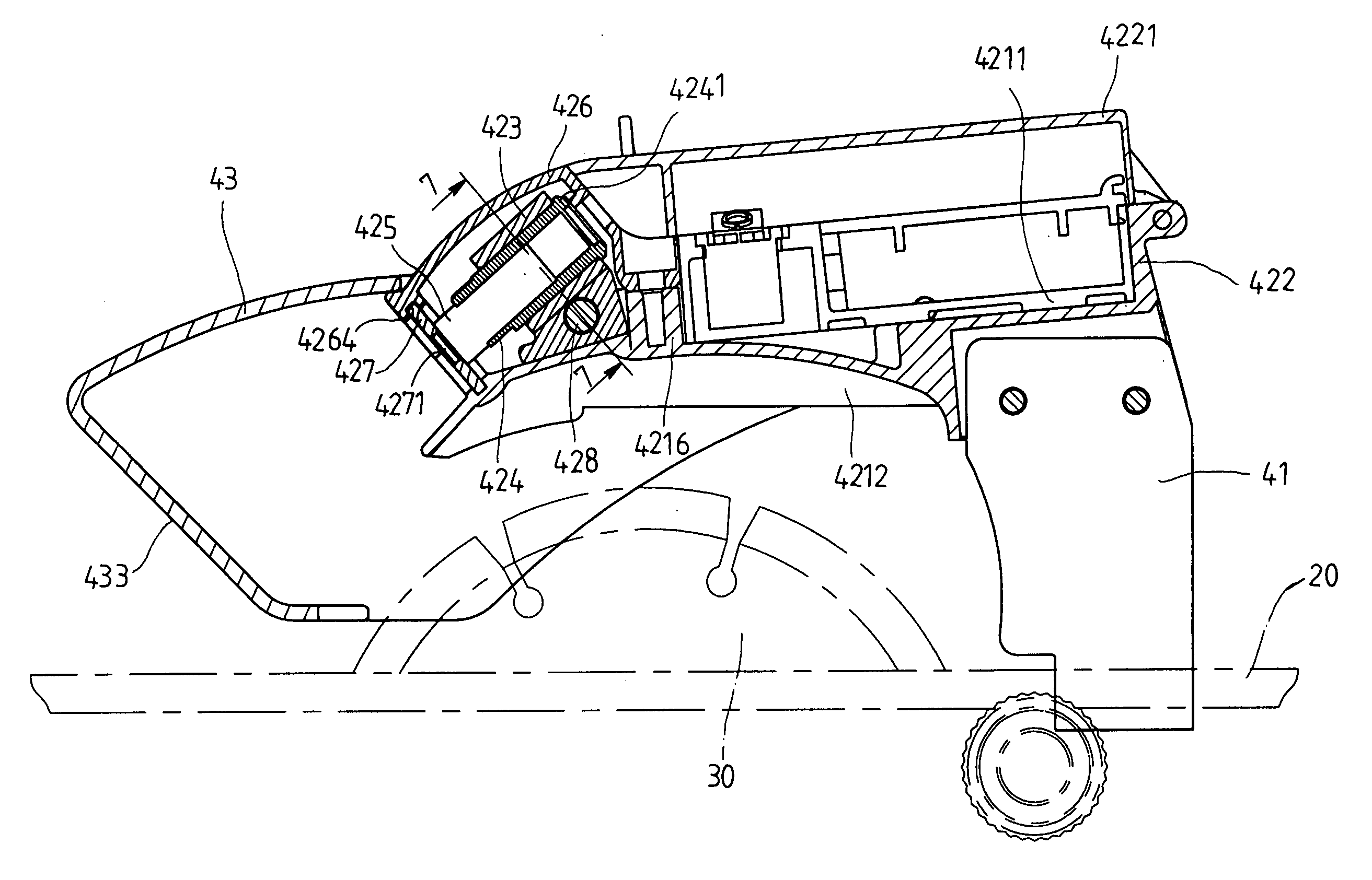
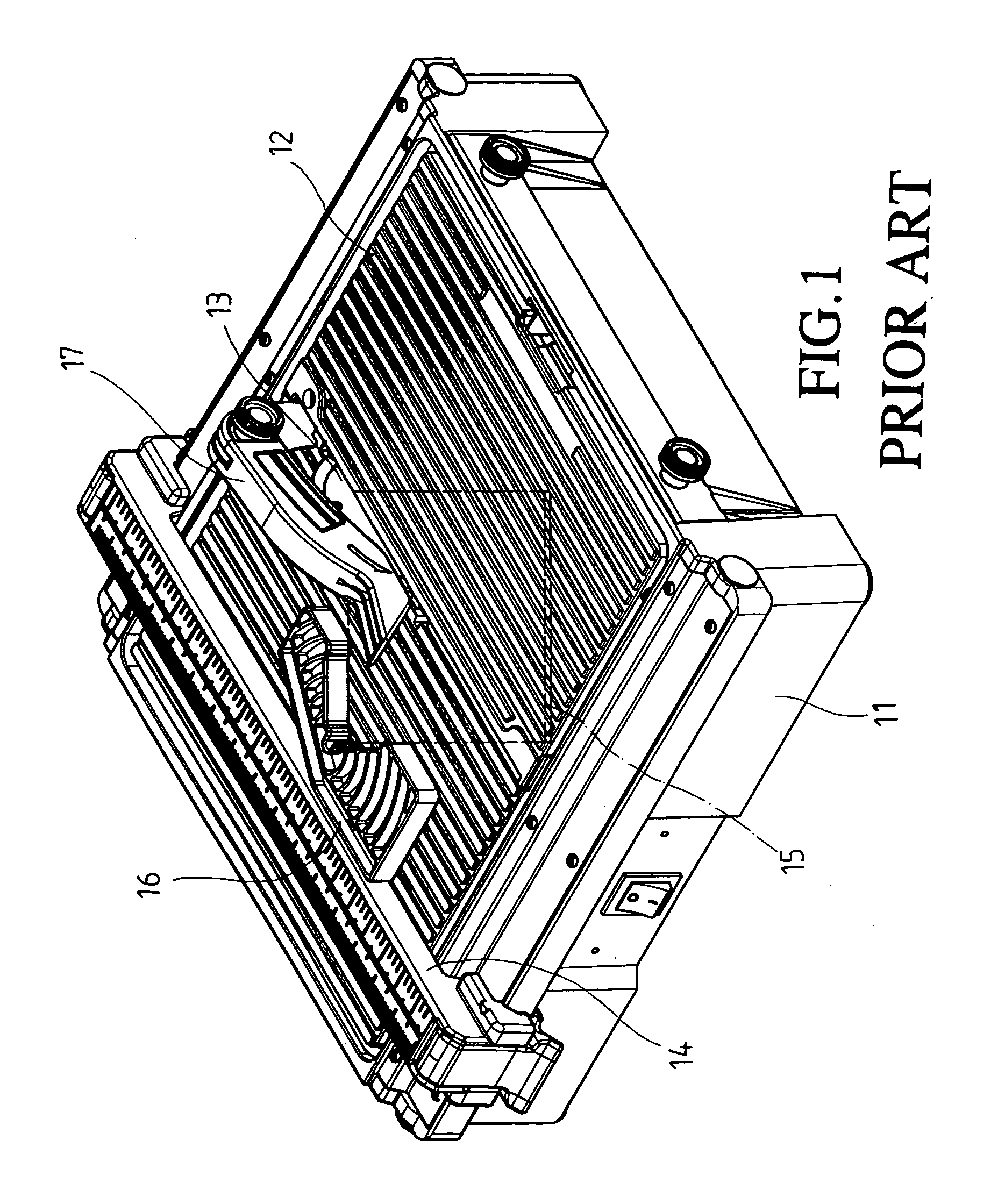
[0013]Referring to FIGS. 1 to 5, the laser guiding device 40 of the present invention is installed on a tile cutting machine which includes a base 20 with a gauge 70 on a side of the base 20 and a rotating blade 30 extends from a top surface of the base 20. The laser guiding device 40 is connected above the rotating blade 30. A clamping device 60 is slidably connected to the gauge 70 so as to clamp a tile 50 and the tile 50 is moved with the clamping device 60.

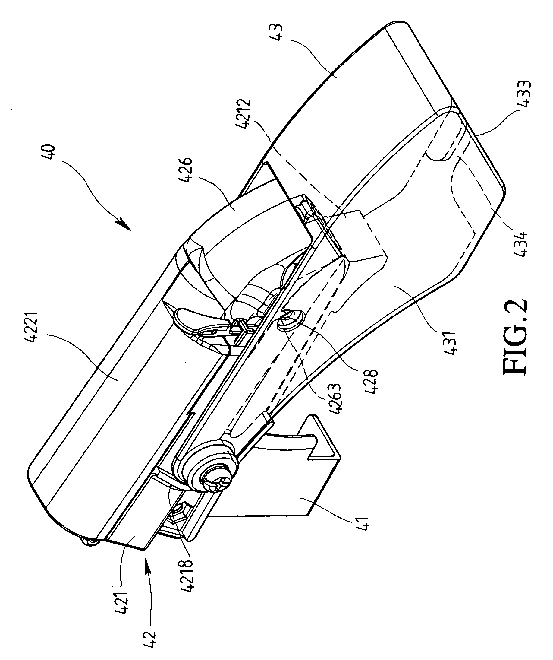
[0014]The laser guiding device 40 comprises a support member 42 which is fixed on the base 20 by an L-shaped member 41 includes a chamber 4211 in which a power supply assembly 422 is received. The power supply 422 has a cover 4221 to covering a top of the assembly 422. Two shafts 4217 extend from two sides of the support member 42 and two curved flanges 4218 are connected on the outside of the two sides of the support member 421. A water seal peripheral wall 4212 extends from an underside of the support member 421 and a lens 4...


PUM

PropertyMeasurementUnit
surface conditionaaaaaaaaaa

Abstract

A laser guiding device is adjustably connected to a support frame on a top of the tile cutting machine and includes a frame in which a laser generating piece is received. An adjusting screw threadedly and transversely extends through the frame and is rotatably connected between two side walls of the support member such that the laser generating piece is moved in the direction of the adjusting screw to generate a laser beam on the tile to be cut. The laser beam is visible regardless of the surface condition of the tile and the debris during cutting.

Description

FIELD OF THE INVENTION[0001]The present invention relates to a laser guiding device adjustably connected to a support member so as to generate a guiding line on the tile to be cut.BACKGROUND OF THE INVENTION[0002]A conventional tile cutting machine used to cut a tile is shown in FIG. 1 and generally includes a base 11 having a top surface 12 on which a tile 15 to be cut is put. A rotating blade 13 is received in a slot defined through the base 11 and a fence 17 is pivotably mounted above the blade 13. A gauge 14 is located on a side of the base 11 and a clamping device 16 is slidably connected to the gauge 14 such that a corner is engaged with the recess in the clamping device 16 and moved together with the clamping device 16 toward the blade 13. A cutting line is pre-set on the surface of the tile 15 so that the user may position the tile 15 by the clamping device 16 properly to allow the blade 13 to cut the tile along the cutting line. Nevertheless, the surface of the tile 15 may ...

Claims


Application Information

Patent Timeline
Patent Type & Authority Patents(United States)
IPC IPC(8): B23D59/00B26D1/18B26D7/00B28D1/04F21V33/00
CPCB23D59/003B28D1/04Y10T83/839
Inventor CHENG, CHIN MINGLIN, CHOU JENQ
Owner MOTOMAX ELECTRIC
Why Eureka
Try Eureka