Planar light source device and liquid crystal display device using the same

a technology of liquid crystal display device and light source device, which is applied in the direction of planar/plate-like light guide, lighting and heating apparatus, instruments, etc., can solve the problems of color shift problem and conventional liquid crystal display device color shift dependent problem, and achieve the effect of less color shi

Inactive Publication Date: 2005-12-20
MITSUBISHI ELECTRIC CORP
View PDF73 Cites 97 Cited by
  • Summary
  • Abstract
  • Description
  • Claims
  • Application Information

AI Technical Summary

Benefits of technology

[0009]Accordingly, an object of the present invention is to provide a liquid crystal display device with less color shift when changing viewing directions, and a planar light source device used for the same.
[0014]A liquid crystal display device according to the present invention has the planar light source device, and a liquid crystal panel placed above an emission surface of the planar light source. The liquid crystal panel has two substrates with a liquid crystal layer interposed therebetween. The liquid crystal display device allows less color shift when changing viewing directions.
[0016]Another planar light source device according to the present invention has a plurality of light sources emitting different colors of light, a light guide plate receiving light from the plurality of light sources at side face to distribute the light over a surface thereof, and a refractor refracting light from the plurality of light sources with different refraction angles for different colors. The planar light source device allows less color shift when changing viewing directions.
[0021]Another liquid crystal display device according to the present invention has the planar light source device, and a liquid crystal panel placed above an emission surface of the planar light source. The liquid crystal panel has two substrates with a liquid crystal layer interposed therebetween. The liquid crystal display device allows less color shift when changing viewing directions.
[0027]Another liquid crystal display device according to the present invention has the planar light source device, and a liquid crystal panel placed above an emission surface of the planar light source. The liquid crystal panel has two substrates with a liquid crystal layer interposed therebetween. The liquid crystal display device allows less color shift when changing viewing directions.

Problems solved by technology

Further, as the angle of viewing direction increases, the luminance differs more significantly depending on wavelength, causing color shift problem.
As described above, the conventional liquid crystal display device has a problem of color shift depending on angles of viewing direction.

Method used


Image

  • Planar light source device and liquid crystal display device using the same
  • Planar light source device and liquid crystal display device using the same
  • Planar light source device and liquid crystal display device using the same

Examples


first embodiment

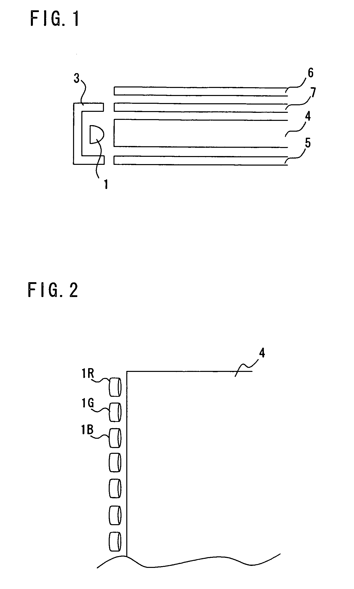
[0045]A configuration of the liquid crystal display device according to the present invention will be explained hereinafter with reference to FIG. 1. FIG. 1 is a sectional view of the liquid crystal display device having red, green, and blue LEDs as light sources. FIG. 2 is an enlarged view of the area of the LEDs. The liquid crystal display device has a LED 1, a reflector 3, a light guide plate 4, a reflection sheet 5, a liquid crystal panel 6, and an optical sheet 7. Reference symbols R, G, and B after the reference numeral indicate red, green, and blue, respectively.

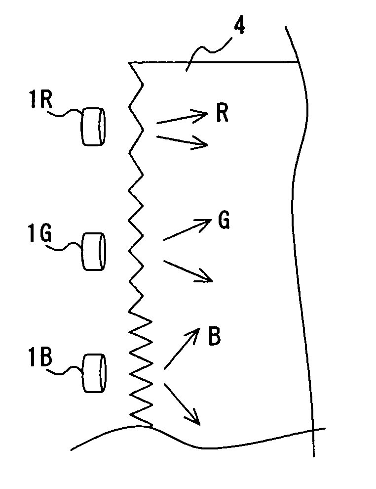
[0046]A plurality of the R, G and B LEDs are provided to produce white light by their combination. The LED 1R emits red light having wavelength λ of approximately 600 to 680 nm, the LED 1G emits green light having wavelength λ of approximately 500 to 600 nm, and the LED 1B emits blue light having wavelength λ of approximately 430 to 500 nm. The light emitted from each color of the LEDs 1 enters a side face of the ligh...

second embodiment

[0054]A planar light source device in the liquid crystal display device according to the second embodiment of the present invention also cancels out the wavelength dependence of transmittance at each viewing direction in the liquid crystal panel 6 shown in FIG. 10 by the wavelength dependence of luminance of emission light at each viewing direction in the planar light source device. The liquid crystal display device thereby exhibits substantially uniform color tone regardless of viewing direction.

[0055]The liquid crystal display device according to the second embodiment will be explained hereinafter with reference to FIG. 5. The same reference numeral as in FIGS. 1 and 2 denotes the same element and redundant description will be omitted. The configuration of the liquid crystal display device according to the second embodiment is substantially the same as the configuration according to the first embodiment shown in FIGS. 1 and 2. The wavelength dependence of transmittance at each vie...

third embodiment

[0059]The liquid crystal display device according to the third embodiment of the present invention will be explained hereinbelow with reference to FIG. 6A. The same reference numeral as in FIGS. 1 and 2 denotes the same element and redundant description will be omitted. In the liquid crystal display device according to the present embodiment, the LEDs 1 of red, green, and blue as light sources are placed in a row along the middle line on the back of the light guide plate 4. The light from the LEDs 1 enters a prism plate 8 directly or after reflected by the reflector 3. In the prism plate 8, the light is spread and transmits through it, then exits from the opposite surface of the entrance surface. The light is reflected by the second reflector 9 to enter the light guide plate 4. The light then exits from the exit surface of the light guide plate 4, and passes through an optical sheet (not shown).

[0060]The spread of the light transmitting through the light guide plate 4 has a dependen...


PUM

PropertyMeasurementUnit
wavelength λaaaaaaaaaa

Abstract

The liquid crystal display device has red, green, and blue LEDs, each emitting a different color light, as a light source. An acrylic lens is mounted on the emission surface of the LED to change angular distributions of light from the LED. The shape of the acrylic lens varies depending on the color of the LED. The angular distribution of emitting light thereby differs by the color of LED to cancel out wavelength dependency of transmittance at each viewing direction in a liquid crystal panel.

Description

BACKGROUND OF THE INVENTION[0001]1. Field of the Invention[0002]The present invention relates to a planar light source device and a liquid crystal display device, and more specifically to a liquid crystal display device with enhanced viewing angle characteristics.[0003]2. Description of Related Art[0004]A liquid crystal display device has a liquid crystal panel comprising two substrates with a liquid crystal layer interposed therebetween. A planar light source device is mounted on the back of the liquid crystal panel. A twisted nematic (TN) mode is widely used in the liquid crystal panel, where liquid crystal molecules are aligned substantially parallel to the substrates in a quiescent state with a twist angle of given value and twist at the substrates according to an applied signal voltage.[0005]A light source of the planar light source device is conventionally a linear cold-cathode tube. Recently, a light emitting diode (LED) also comes into use because of its longer life and good...

Claims


Application Information

Patent Timeline
Patent Type & Authority Patents(United States)
IPC IPC(8): F21V8/00G02F1/13357F21Y101/02G02B6/00
CPCG02B6/0026G02B6/0016G02B6/0001G02F1/1335
Inventor OHTSUKI, HIDEYONAKANISHI, KUNIFUMIYONEDA, TOSHIYUKI
Owner MITSUBISHI ELECTRIC CORP
Why Eureka
Try Eureka