Flue cap

a technology of pipe ends and flues, applied in the direction of caps, heating types, lighting and heating apparatus, etc., can solve the problems of affecting the pressure control, nuisance lockout, and inability to project upwardly the pipe ends to environmental elements

Active Publication Date: 2005-12-27
K & M PLASTICS
View PDF15 Cites 28 Cited by
  • Summary
  • Abstract
  • Description
  • Claims
  • Application Information

AI Technical Summary

Problems solved by technology

Usually, just leaving upwardly projecting pipe ends exposed to environmental elements is unacceptable.
In an exhaust line for a high efficiency furnace, for example, this environmental contamination can adversely affect the pressure controls that are designed to safely monitor the removal of combustion by-products from the building living spaces.
An overly restricted flow passage can, at the best, cause nuisance lockouts of the furnace controls because of the high head pressure or can, at the worst, create unintended flow paths of the flue gases within or around the furnace.
Accordingly, a building owner cannot afford to simply rely on a contractor's judgment which might haphazardly or arbitrarily construct such a shielding device.

Method used


Image

  • Flue cap
  • Flue cap
  • Flue cap

Examples


Embodiment Construction

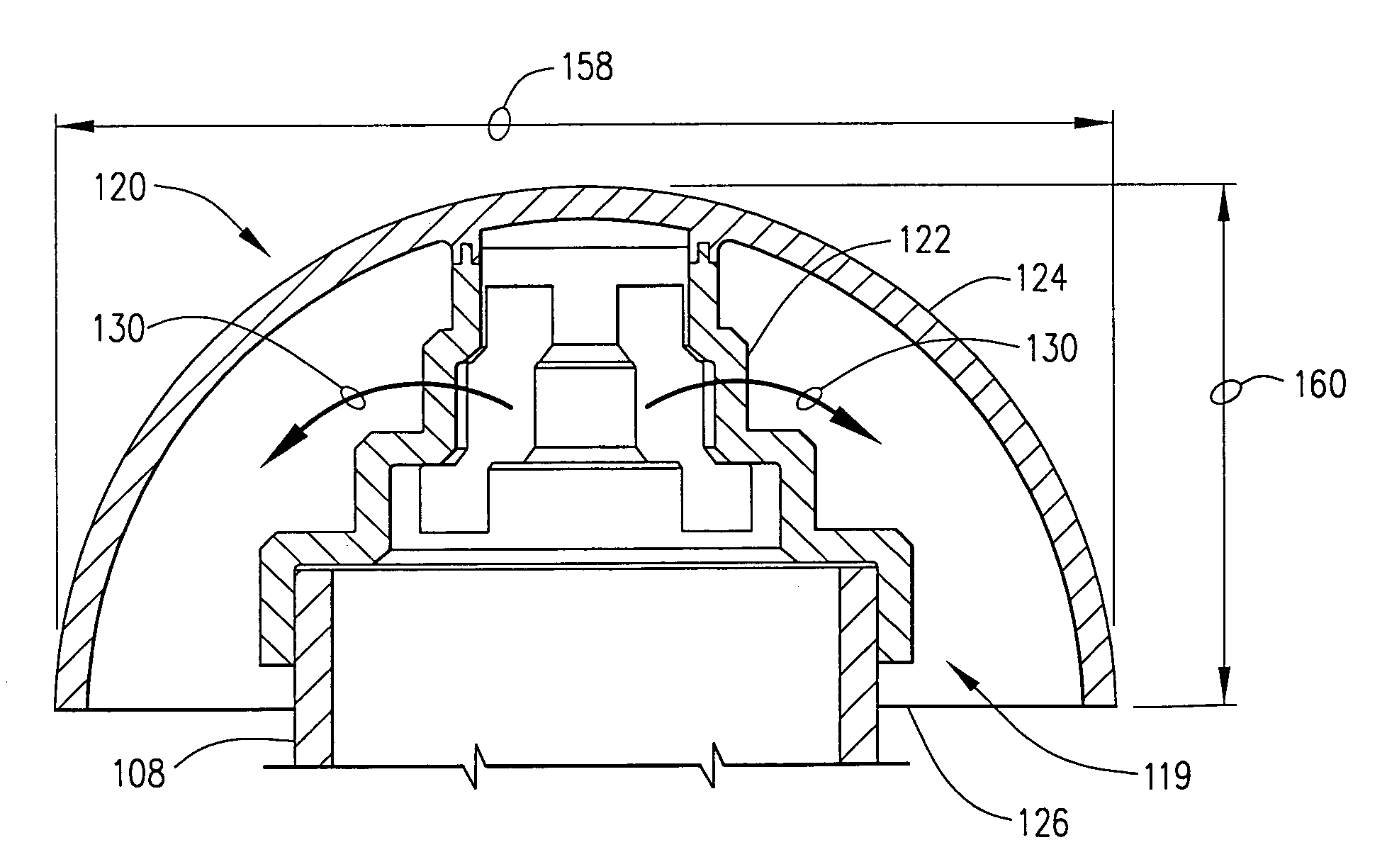
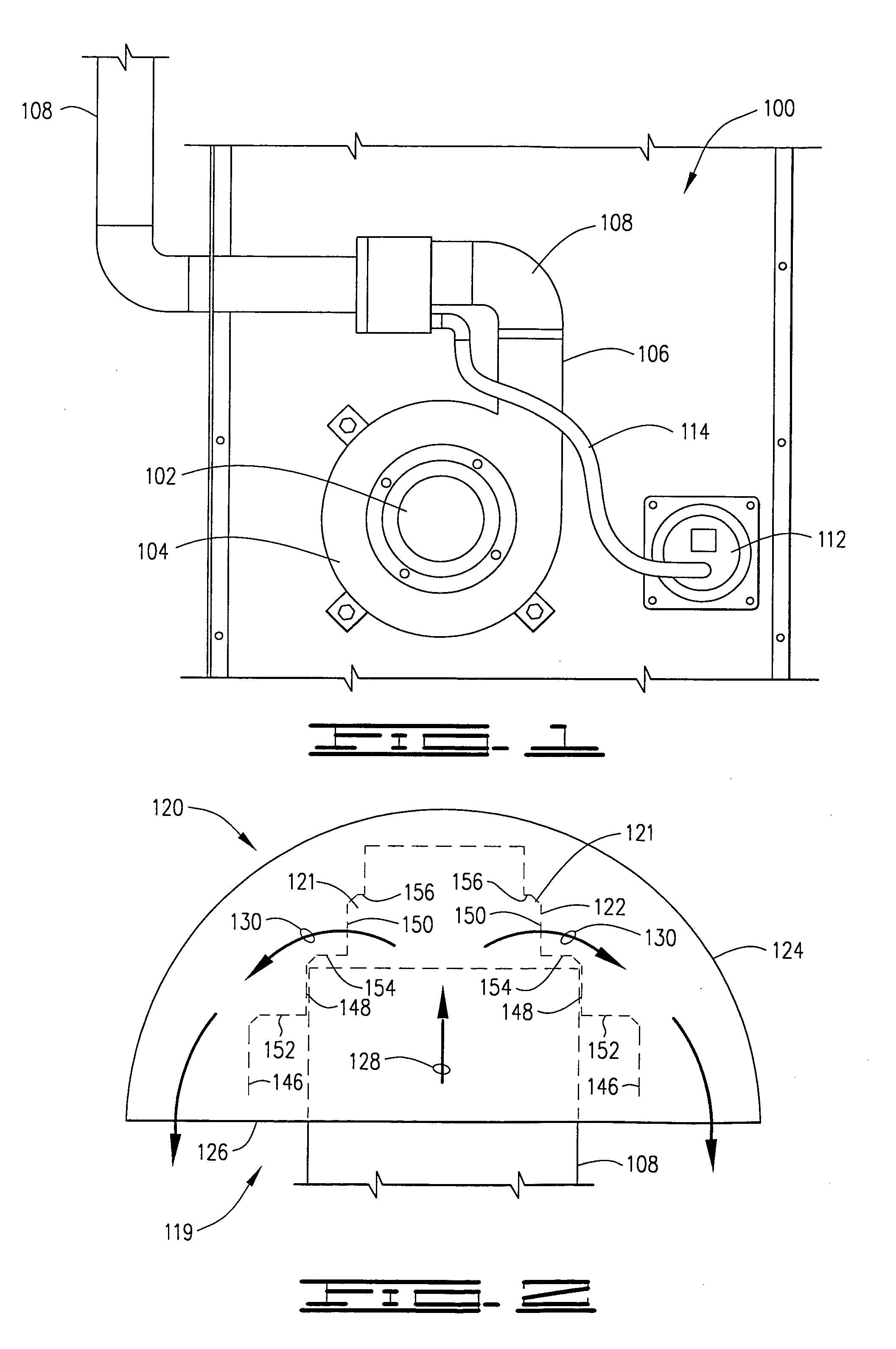
[0022]FIG. 1 is an elevational view of portion of a gas furnace 100 that is suited for use in practicing the embodiments of the present invention. The furnace 100 has an inducer motor 102 (sometimes called a ventor motor) for drawing combustion by-products (or flue gases) from a combustion area (not shown). The motor 102 drives as impeller (not shown) inside a housing 104 that is in fluid communication with the combustion area. The rotating impellor draws flue gases from the combustion area and through as outlet 106 portion of the housing 104. A conduit 108, or “pipe”108 or more particularly in some embodiments “flue”108, is connected to the outlet 106 at a proximal end thereof, and extends away from the furnace 100 to remove the flue gases from the inhabited living spaces served by the furnace 100. Typically, the pipe 108 terminates after passing through a penetration in either an exterior wall or the roof.

[0023]In the illustrative use employed with the furnace 100 of FIG. 1 the co...


PUM


Abstract

A flue cap is provided comprising a body defining a plurality of attachment surfaces adapted for selectively matingly engaging a selected flue from a plurality of different size flues. The flue cap comprises a polymer material defining an attachment surface that is adapted for a close mating engagement with an outer diameter of the selected flue and defines an aperture establishing a passageway in fluid communication with the flue and passing through the cap. A flue assembly is constructed by steps comprising providing an open end of the flue; providing a flue cap comprising a polymer material defining an attachment surface that is adapted for a close mating engagement with an outer diameter of a flue, bonding the flue cap to the flue with an adhesive; and flowing a fluid out the open end of the flue and through the flue cap.

Description

CLAIM OF PRIORITY[0001]This application claims the benefit of United States provisional patent application Ser. No. 60 / 541,551 filed Feb. 4, 2004.FIELD OF THE INVENTION[0002]This invention relates generally to the field of pipe components and more particularly without limitation to a pipe cap for shielding the open end of a pipe from environmental elements.BACKGROUND OF THE INVENTION[0003]There are a number of instances in building construction where a conduit, such as a round pipe, is routed to atmosphere at an open distal end. The roof of virtually any commercial or residential building will typically have one or more penetrations through which such pipes project. Some of these pipes are used for venting, such as for plumbing drains, furnace exhausts, and the like.[0004]Usually, just leaving upwardly projecting pipe ends exposed to environmental elements is unacceptable. Left unshielded, rain, snow, dirt and debris will enter the open end and travel into the equipment at the other...

Claims


Application Information

Patent Timeline
Patent Type & Authority Patents(United States)
IPC IPC(8): B65B31/00F16L55/10F16L55/115F23L17/02
CPCF16L55/115
Inventor BROWN, KENNETH J.BROWN, TAMMY D.TEMPLE, MARK A.
Owner K & M PLASTICS
Why Eureka
Try Eureka