Apparatus for elevator group control

Inactive Publication Date: 2005-12-27
MITSUBISHI ELECTRIC CORP
View PDF13 Cites 22 Cited by
  • Summary
  • Abstract
  • Description
  • Claims
  • Application Information

AI Technical Summary

Benefits of technology

[0024]Also in this invention, both cars can ascend and descend freely in their own priority zones, therefore, it is possible to cause the cars display high transportation efficiency. Furthermore, when a car enters the priority zone of a counterpart car, the upper car or the lower is caused to make an entry after a judgment is formed on entry propriety. Therefore, it is possible to avoid the mutual interference of the upper car

Problems solved by technology

Furthermore, because it is ensured that after a response to a call in the common-use zone, a car is caused to escape from the common-use zo

Method used


Image

  • Apparatus for elevator group control
  • Apparatus for elevator group control
  • Apparatus for elevator group control

Examples


first embodiment

[0037]FIG. 1 to FIG. 8 show the first embodiment of a preferred apparatus for elevator group control related to the present invention.

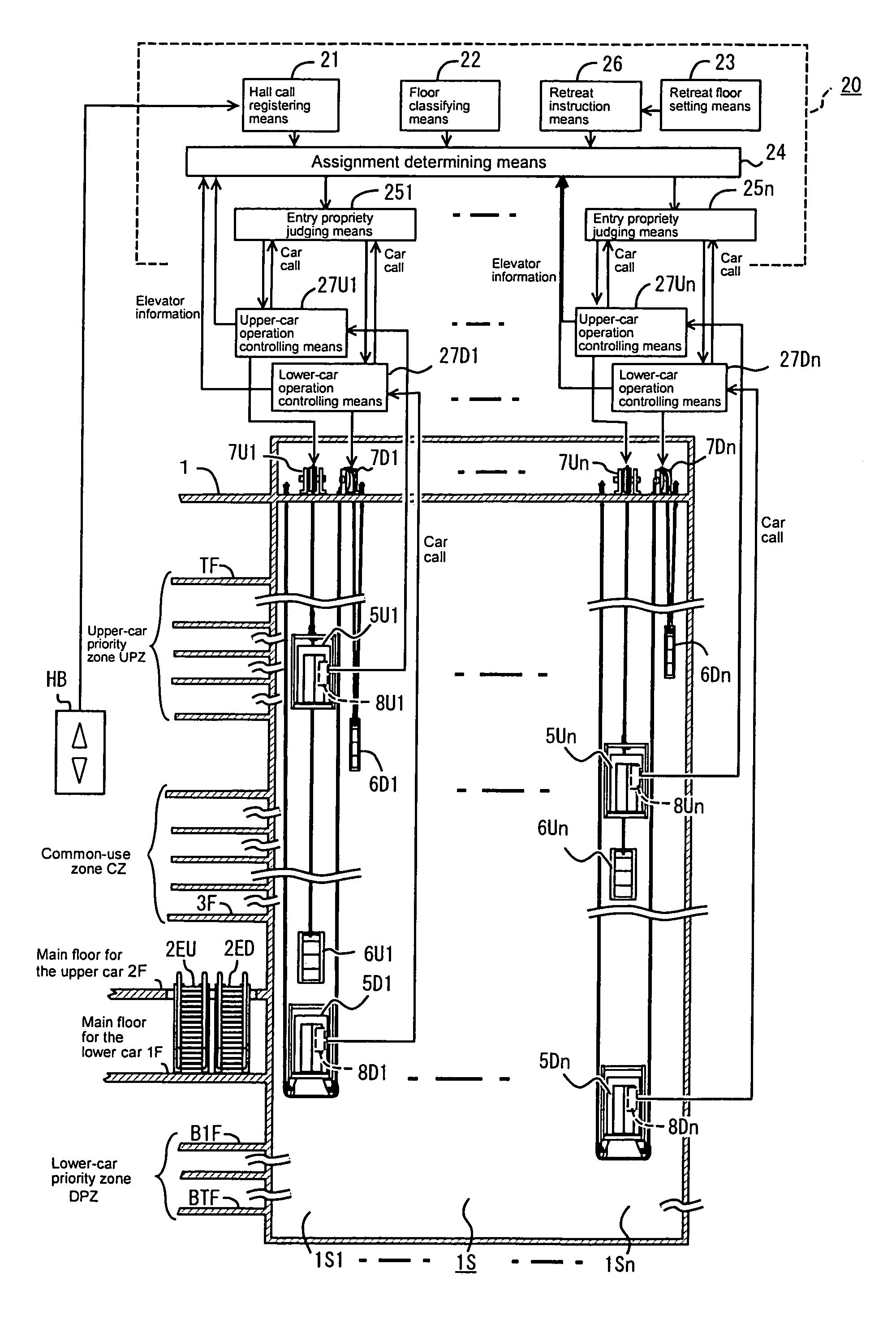
[0038]FIG. 1 is a block diagram showing the configuration of an apparatus for elevator group control. Reference numeral 1 denotes a building in which n sets of elevators, each set consisting of an upper car and a lower car, and reference numeral 1S denotes a shaft in which n sets of elevators are housed and this shaft is constituted by a shaft 1S1 for the first set to a shaft 1n1 for the n-th set.

[0039]Reference numeral 5U1 denotes an upper car disposed within the shaft 1S1 for the first set, reference numeral 5D1 denotes a lower car disposed immediately below the upper car 5U1, reference numeral 6U1 denotes a balancing weight of the upper car 5U1, and reference numeral 6D1 denotes a balancing weight of the lower car 5D1. Reference numeral 7U1 denotes a hoisting machine which causes the upper car 5U1 to ascend and descend and reference numeral 7D1 den...

second embodiment

[0110]In this second embodiment, the common-use zone CZ in the first embodiment is added to the lower-car priority zone DPZ. Therefore, this embodiment is suitable for a building in which an equipment floor, for example, is provided between the lower-car priority zone DPZ and the upper-car priority zone UPZ, and there is scarcely any mutual traffic between the two zones.

[0111]FIGS. 9(a) to 9(d) to FIG. 11 show a preferred apparatus for elevator group control related to the second embodiment of the present invention.

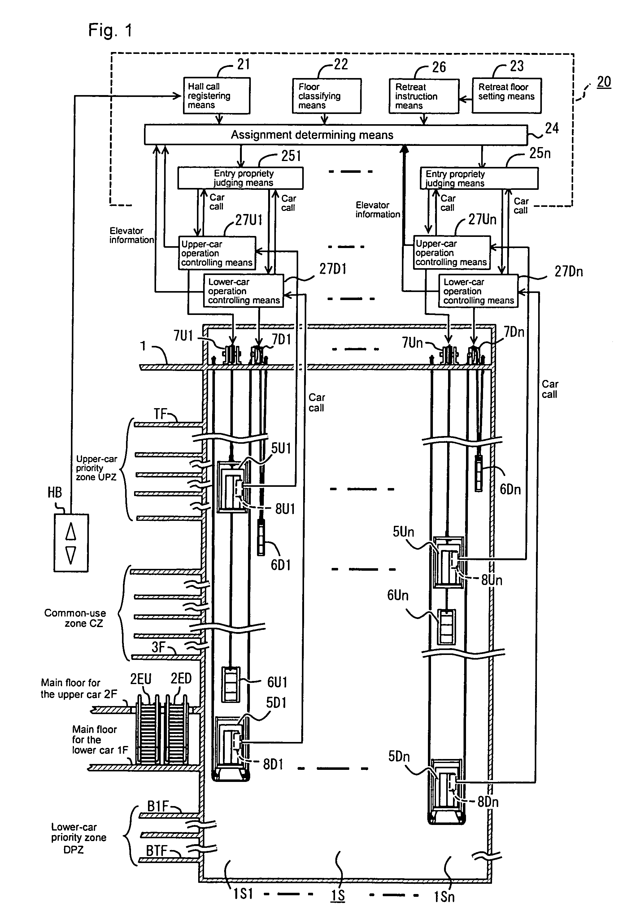
[0112]Incidentally, the configuration of the apparatus for elevator group control shown in FIG. 1 and the control circuit of the apparatus for elevator group control shown in FIG. 2 are used as they are.

[0113]FIGS. 9(a) to 9(d) are explanatory diagrams showing the operation of the upper car 5U and the lower car 5D and the common-use zone CZ of FIGS. 4(a) to 4(d) is added to the lower-car priority zone DPZ. Therefore, with the exception that UP hall calls on the third floo...


PUM


Abstract

In an apparatus for elevator group control which performs group management of a set of elevators, the set consisting of an upper car and a lower car which are disposed in a vertical relation within one elevator shaft and which ascend and descend independently, the floors are classified so that a floor communicating with an entrance of a building is classified as a main floor for the lower car, a floor communicating with an entrance of the building above the main floor for the lower car is classified as a main floor for the upper car, a lower-floor portion of the shaft is classified as a lower-car priority zone, an upper-floor is classified as an upper-car priority zone, and an intermediate-floor portion is classified as a common-use zone of the upper car and the lower car. A hall call is assigned to the upper car or the lower car according to the classification to which the hall in question belongs. In each of the priority zones, the upper car or the lower car is preferentially brought into service. In the common-use zone, after the existence or nonexistence of interference with a counterpart car is determined, the upper car or the lower car is caused to make an entry and is brought into service and, after a response, the upper car or the lower car is caused to escape from the common-use zone and is caused to retreat to an escape floor.

Description

TECHNICAL FIELD[0001]The present invention relates to an apparatus for group control of a set or a plurality of sets of elevators consisting of an upper car and a lower car which are disposed in a vertical relation within one elevator shaft and which ascend and descend independently, while avoiding mutual interference of the cars.BACKGROUND ART[0002]In conventional elevators, a shaft was usually provided for each elevator and one car was housed in one shaft. Therefore, in a case where a plurality of elevators are installed, shafts for the number of elevators were juxtaposed and hence each car could ascend and descend freely without interfering with other cars. In such an installed condition, a plurality of elevators were subjected to group control for an improvement in transportation efficiency.[0003]Incidentally, in a high-rise building where a large number of elevators are installed, installing a shaft for each car posed the problem that the ratio of the area of the shaft portion ...

Claims


Application Information

Patent Timeline
IPC IPC(8): B66B1/14B66B1/18B66B1/24
CPCB66B1/18B66B11/0095Y10S187/902
Inventor HIKITA, SHIRO
Owner MITSUBISHI ELECTRIC CORP
Why Eureka
Try Eureka