
Shuttle van system for container terminal and method for transporting containers using same

a container terminal and shuttle van technology, applied in the direction of transportation items, loading/unloading vehicle arrangment, refuse collection, etc., can solve the problems of subsequent reversal operations and inefficient straddle carriers, and achieve the effect of low energy consumption and high transportation efficiency

Active Publication Date: 2015-04-09
TIANJIN PORT (GROUP) COMPANY
View PDF5 Cites 2 Cited by
  • Summary
  • Abstract
  • Description
  • Claims
  • Application Information

AI Technical Summary

Benefits of technology

The objective of this patent is to provide a shuttle van system and method for transporting containers in a container terminal with high efficiency, low energy consumption, and suitable for long distance transportation. The main technical effects of the patent are as follows: a more efficient and energy-saving shuttle van system and method for container transportation, a reduction in operation cost through the use of the shuttle van instead of a yard crane, and the use of a supporting plate and second transition platform for container loading and unloading.

Problems solved by technology

However, straddle carriers are not very efficient and may require subsequent reversing operations during dispatching.

Method used


Image

  • Shuttle van system for container terminal and method for transporting containers using same
  • Shuttle van system for container terminal and method for transporting containers using same
  • Shuttle van system for container terminal and method for transporting containers using same

Examples


example 1

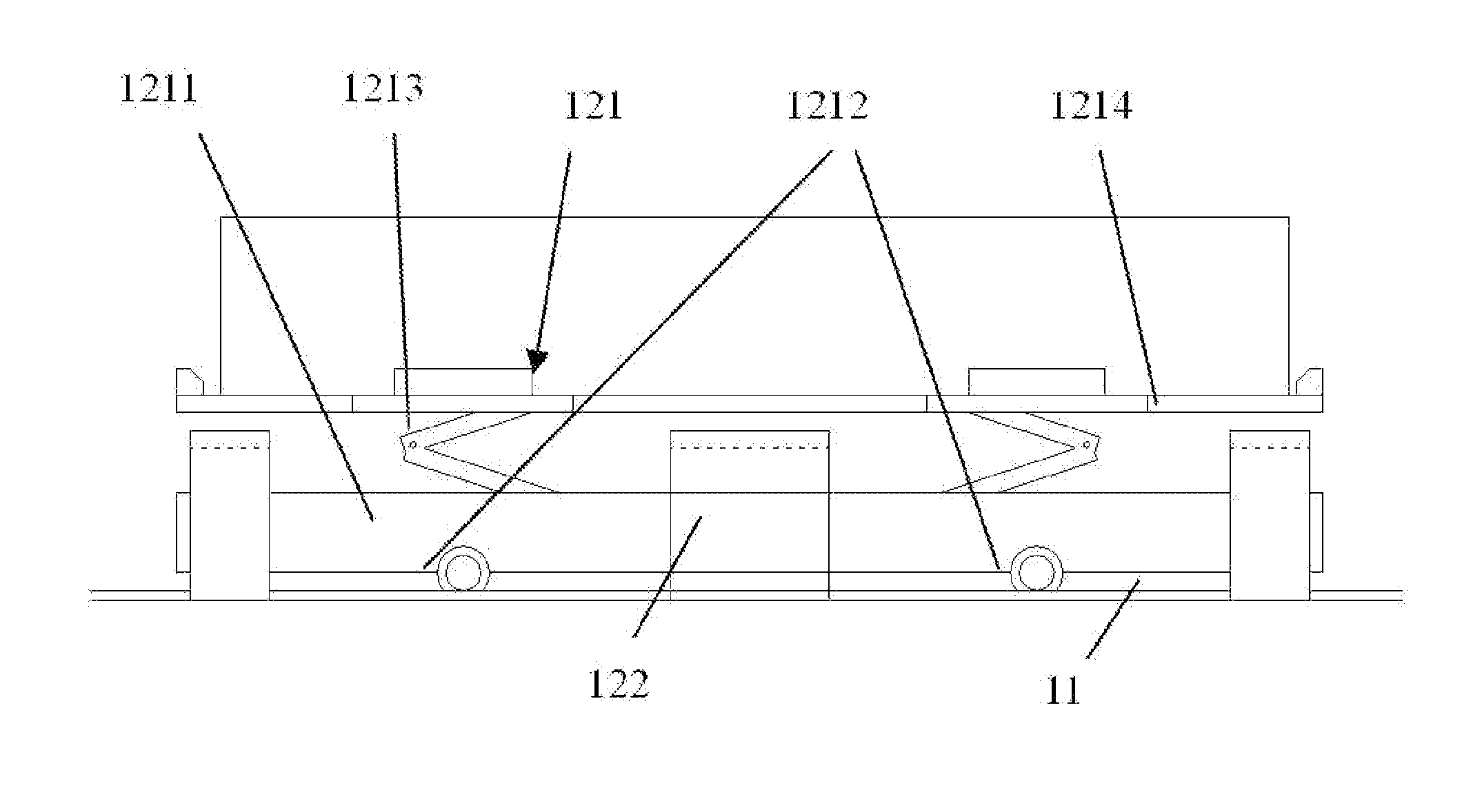
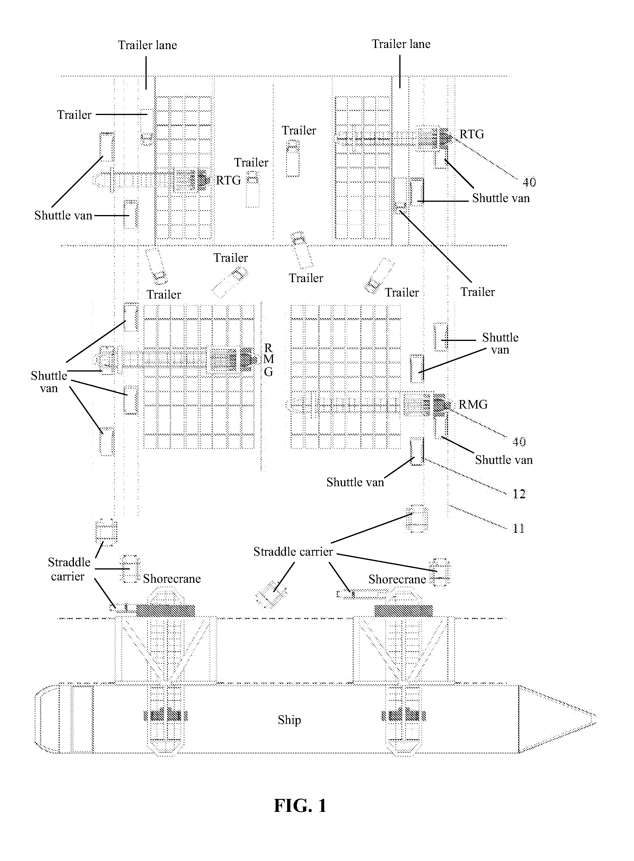
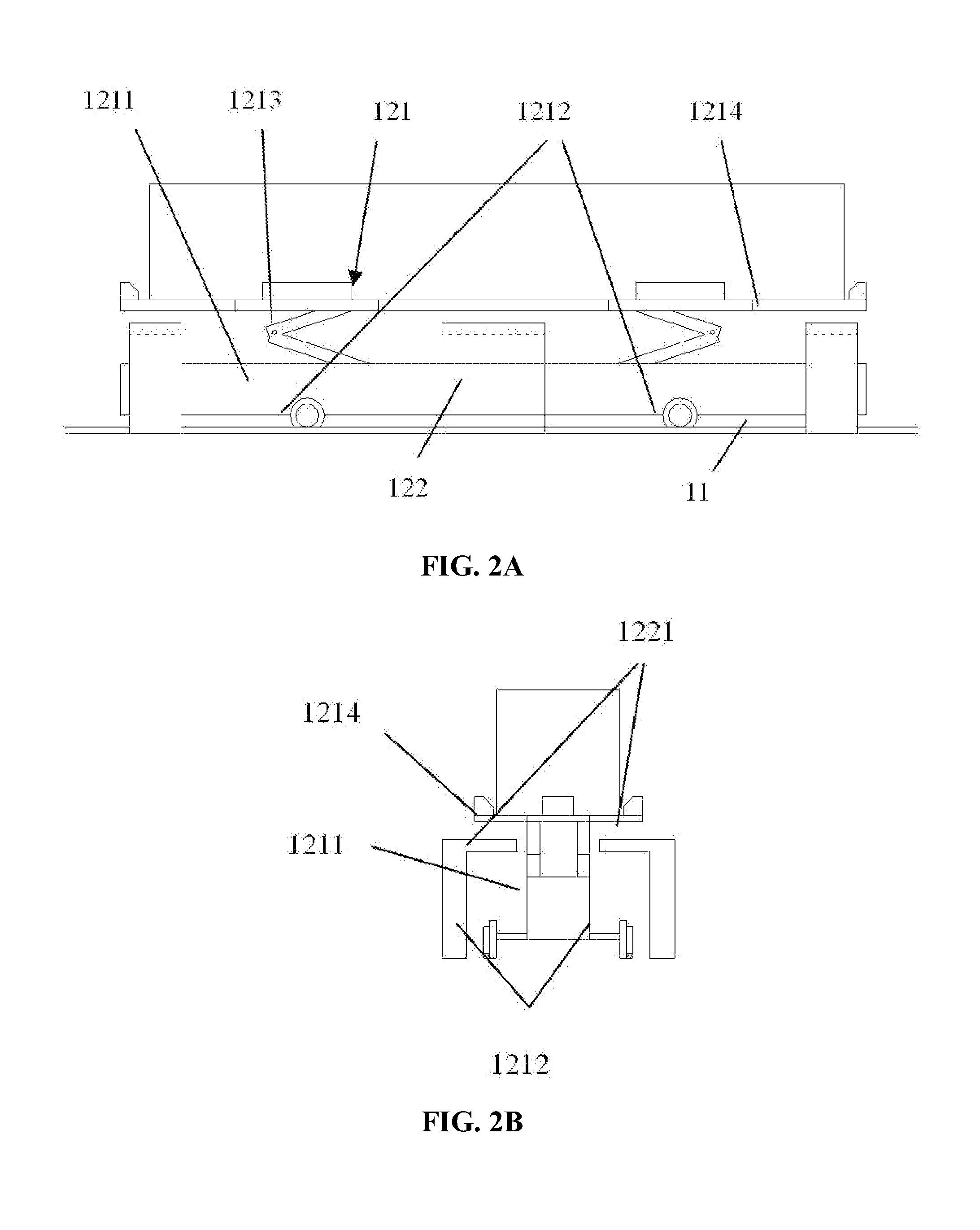
[0051]As shown in FIGS. 1, 2A, 2B, 3A, and 3B, a shuttle van system for a container terminal comprises: four rail groups 11 disposed in a direction vertical to a quay frontage and passes through a storage yard and transfer devices 12 disposed on the rail groups for transferring containers. Two rail groups 11 are disposed at a left side of the storage yard back to the quay frontage, and another two rail groups 11 are disposed at a right side of the storage yard back to the quay frontage. The four rail groups 11 are disposed beneath yard cranes 40. A working radius of each yard crane 40 is extended to the rail group and a container stacking zone of the storage yard.

[0052]The transfer device 12 comprises a plurality of shuttle vans 121 running on the rail groups and a plurality of transition platforms 122 arranged along the rail groups. Each rail group is provided with three transition platforms 122 and two shuttle vans 121.

[0053]Each shuttle van 121 comprises: a base frame 1211, a whe...

example 2

[0068]As shown in FIGS. 1, 4A, 4B, 5A, and 5B, a shuttle van system for a container terminal comprises: four rail groups 11 disposed in a direction vertical to a quay frontage and passes through a storage yard and transfer devices 12 disposed on the rail groups for transferring containers. Two rail groups 11 are disposed at a left side of the storage yard back to the quay frontage, and another two rail groups 11 are disposed at a right side of the storage yard back to the quay frontage. The four rail groups 11 are disposed beneath yard cranes 40. A working radius of each yard crane 40 is extended to the rail group and a container stacking zone of the storage yard.

[0069]The transfer device 12 comprises a plurality of shuttle vans 123 running on the rail groups and a plurality of transition platforms 124 arranged along the rail groups. Each rail group is provided with three transition platforms 124 and two shuttle vans 123.

[0070]Each shuttle van 123 comprises: a base frame 1231, a whe...


PUM


Abstract

A shuttle van system for a container terminal, including: at least one rail and a transfer device. The transfer device includes a plurality of shuttle vans and a plurality of transition platforms. Each shuttle van includes: a base frame, a wheel group, a wheel driving device, a lifting device, and a supporting plate. Each transition platform includes brackets. The shuttle vans run on the rail between the brackets. The lifting device of the shuttle van is configured to lift the container from the supporting plate. The container is transferred from the supporting plate of the shuttle van to the bracket after contraction of the lifting device.

Description

CROSS-REFERENCE TO RELATED APPLICATIONS[0001]This application is a continuation-in-part of International Patent Application No. PCT / CN2014 / 072535 with an international filing date of Feb. 26, 2014, designating the United States, now pending, and further claims priority benefits to Chinese Patent Application No. 201310135264.3 filed Apr. 18, 2013. The contents of all of the aforementioned applications, including any intervening amendments thereto, are incorporated herein by reference. Inquiries from the public to applicants or assignees concerning this document or the related applications should be directed to: Matthias Scholl P. C., Attn.: Dr. Matthias Scholl Esq., 245 First Street, 18th Floor, Cambridge, Mass. 02142.BACKGROUND OF THE INVENTION[0002]1. Field of the Invention[0003]The invention relates to the field of loading and unloading of containers in a container terminal, and more particularly to a shuttle van system for a container terminal and a method for transporting contai...

Claims


Application Information

Patent Timeline
Patent Type & Authority Applications(United States)
IPC IPC(8): B65G63/02B60P1/44B65G67/24B61D47/00B65G67/04B60P1/02B61D3/20
CPCB65G63/025B60P1/02B60P1/4442B60P1/4485B65G2814/0313B61D47/00B65G67/04B65G67/24B65G2811/09B61D3/20B65G63/065
Inventor LI, WEILI, XUNAN, GUOLIZHU, LIANYILV, QINGXINYANG, RONGLI, QIANG
Owner TIANJIN PORT (GROUP) COMPANY
Learn More