Adjustable damper with control valve, mounted in an external collar

a technology of control valve and damper, which is applied in the direction of shock absorbers, vibration dampers, springs/dampers, etc., can solve the problems of difficulty or awkwardness in effectively positioning the respective inlet and outlet of the externally mounted control valv

Inactive Publication Date: 2005-12-27
TENNECO AUTOMOTIVE OPERATING CO INC
View PDF6 Cites 91 Cited by
  • Summary
  • Abstract
  • Description
  • Claims
  • Application Information

AI Technical Summary

Problems solved by technology

However, often it is difficult or awkward to effectively locate the respective inlet and outlet of the externally mounted control valve onto the outer housing of the shock absorber during assembly on a repeatable basis.

Method used


Image

  • Adjustable damper with control valve, mounted in an external collar
  • Adjustable damper with control valve, mounted in an external collar
  • Adjustable damper with control valve, mounted in an external collar

Examples


Embodiment Construction

[0013]The following description of the preferred embodiment(s) is merely exemplary in nature and is in no way intended to limit the invention, its application, or uses.

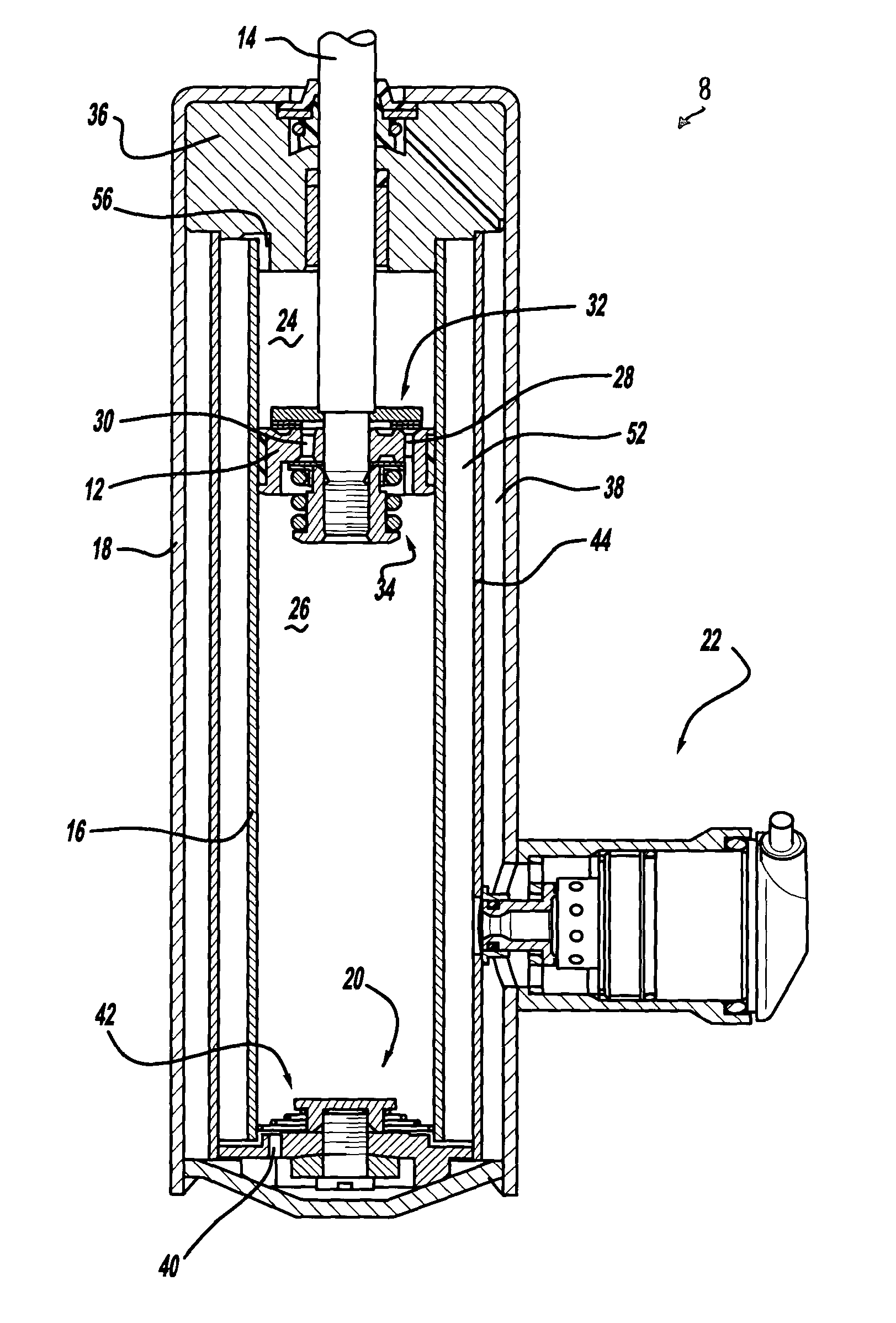
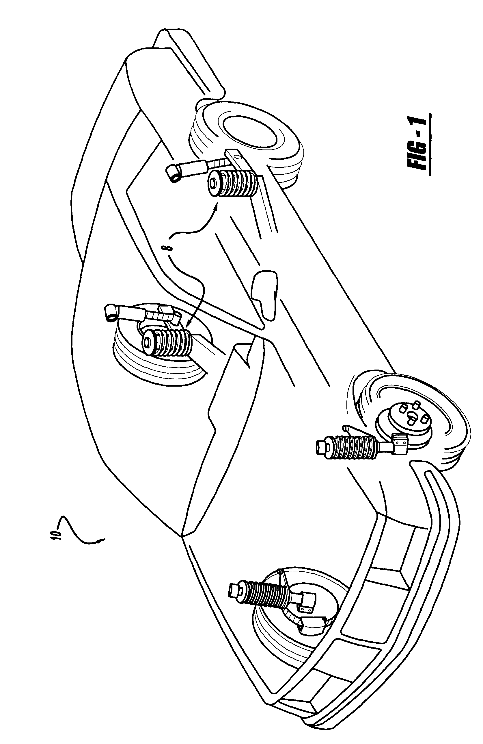
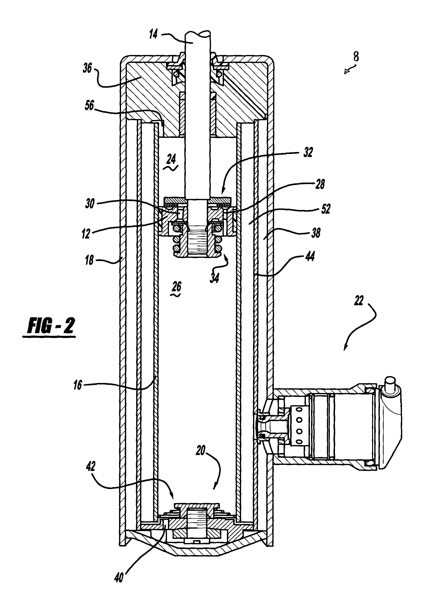
[0014]Referring now to the drawings in which like reference numerals designate like components throughout the several views, there is shown in FIG. 1 a shock absorber according to the teachings of the present invention which is designated generally by the reference numeral 8. The shock absorber 8 is shown in a mounted position in a vehicle 10. While shock absorber 8 is illustrated as being mounted to the rear suspension of vehicle 10, it is within the scope of the present invention to utilize the features of shock absorber 8 on the front suspension of vehicle 10 if desired. Referring to FIG. 2, the shock absorber 8 is a triple tube shock absorber which comprises a piston 12, a piston rod 14, a pressure tube 16, a reserve tube or outer housing 18, a base valve assembly 20 and an externally mounted control valve 22. The...


PUM


Abstract

A shock absorber according to the present invention includes a pressure tube having a working chamber disposed therewithin. A piston is slidably disposed within the working chamber and divides the working chamber into an upper working chamber and a lower working chamber. An intermediate tube is disposed around the pressure tube and the working chamber to define an intermediate chamber. A reserve tube is disposed around the intermediate tube. A collar is attached to the intermediate tube. The collar is defined by a shoulder portion extending generally lateral to the intermediate tube and a radial neck portion extending generally perpendicularly to the intermediate tube. An external control valve includes a valve seat received within the collar in an installed position. The external control valve is attached to the reserve tube.

Description

FIELD OF THE INVENTION[0001]The present invention relates to a hydraulic damper or shock absorber adapted for use in a suspension system such as the suspension systems used for automotive vehicles. More particularly, the present invention relates to a shock absorber having an external control valve mounted in an external collar of the shock absorber.BACKGROUND OF THE INVENTION[0002]A conventional hydraulic damper or shock absorber comprises a cylinder which is adapted at one end for attachment to the sprung or unsprung mass of a vehicle. A piston is slidably disposed within the cylinder with the piston separating the interior of the cylinder into two fluid chambers. A piston rod is connected to the piston and extends out of one end of the cylinder where it is adapted for attachment to the other of the sprung or unsprung mass of the vehicle. A first valving system is incorporated within the piston as a safety hydraulic relief valve during the shock absorber's extension stroke of the ...

Claims


Application Information

Patent Timeline
Patent Type & Authority Patents(United States)
IPC IPC(8): F16FF16F9/32F16F9/34F16F9/54
CPCF16F9/325
Inventor HOLIVIERS, DAVID
Owner TENNECO AUTOMOTIVE OPERATING CO INC
Why Eureka
Try Eureka