Drawer interlock mechanism

a technology of interlocking mechanism and drawing rod, which is applied in the direction of building locks, construction, construction fastening devices, etc., can solve the problems of high manufacturing cost, many components involved, and complicated design, and achieve the effect of reducing manufacturing cost and assembly time, simplifying the design of the positioning mechanism of the axial cam, and facilitating assembly

Active Publication Date: 2005-12-27
NAN JUEN INT CO LTD
View PDF10 Cites 19 Cited by
  • Summary
  • Abstract
  • Description
  • Claims
  • Application Information

AI Technical Summary

Benefits of technology

[0006]The present invention aims to improve the deficiency of the above-mentioned traditional drawer interlock mechanism based on user's demands, so the design for the positioning mechanism of axial cam is simplified. Furthermore, the assembly will be facilitated by the new connection components to effectively reduce manufacturing cost and assembly time. As a result, the product competitiveness will be significantly improved and benefit the industry.

Problems solved by technology

Thus, such a way to achieve positioning of the axial cam 12′ in 90-degree rotation involves many components and complicated design.
This causes a tedious process of assembly and relatively high manufacturing cost, which lowers the product competitiveness.
Because the braking slide 13′ has one sticking positioning component 131′ on one side that needs special orientation for assembly, it causes inconvenience.
Furthermore, when the drawer interlock mechanism 1′ is integrated with the slide 2′ and the rail 3′ to form a single unit configuration, the entire unit is placed on the drawer and the two braking slides 13′ do not provide effective blockage.
It requires separate assembly for the braking slide 13′ and takes much labor.

Method used


Image

  • Drawer interlock mechanism
  • Drawer interlock mechanism
  • Drawer interlock mechanism

Examples


Embodiment Construction

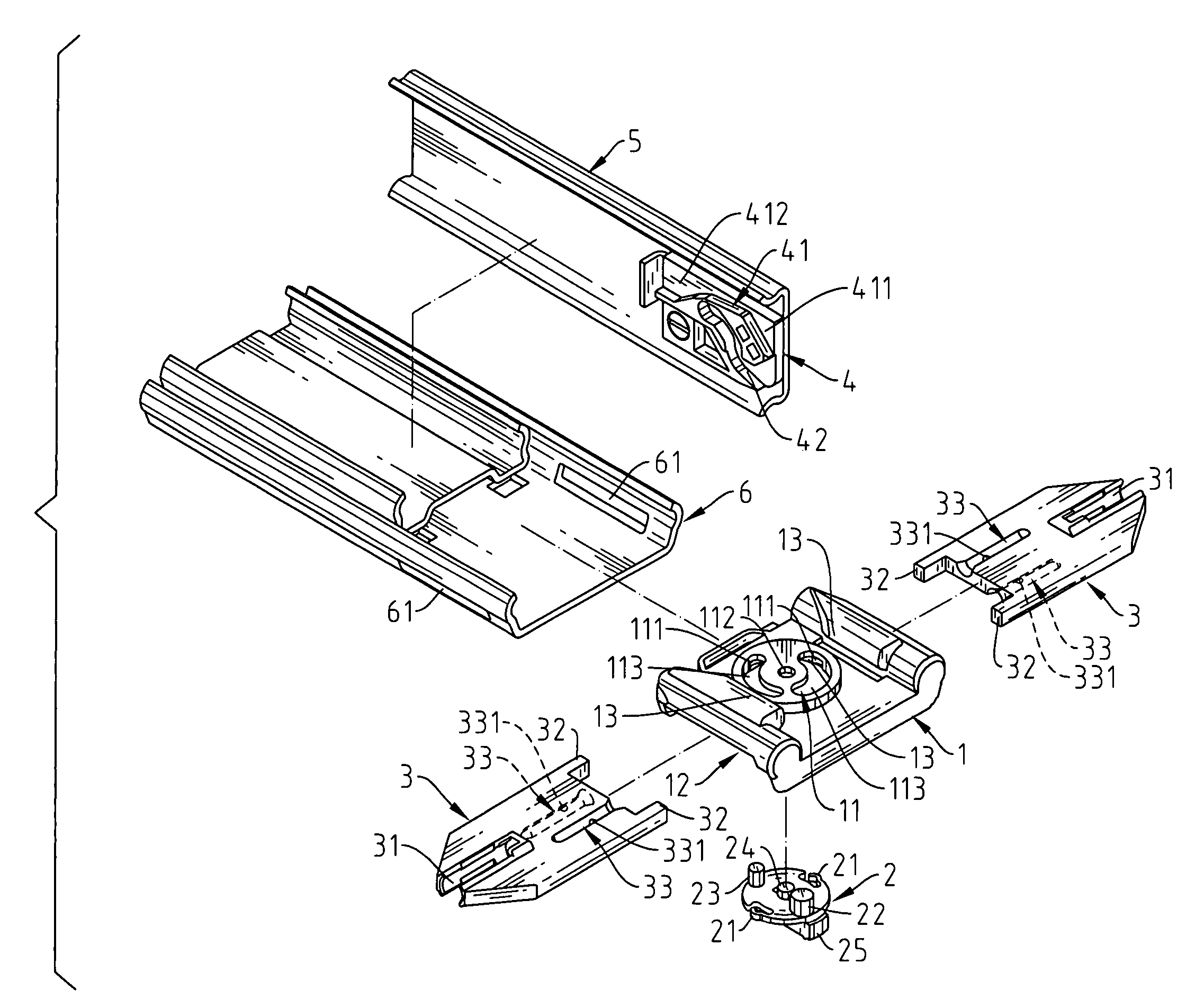
[0022]Please refer to the figures from FIG. 6 to FIG. 15. The drawer interlock mechanism in the present invention mainly comprises a fixation base 1, an axial cam 2, two braking slides 3 and a guiding switch 4.

[0023]The fixation base 1 is fixed at one end of the rail 6. In the center of the fixation base 1, there is the holding groove 11, which has concave openings 111 every 90-degree angle along the inner periphery. There is a penetrating hole 112 in the center of top face along with two corresponding position-limiting curved grooves 113. At the bottom of the fixation base 1, there is a slide groove 12 in longitudinal direction. On the each side of the slide grooves 12, there is a convex point 121. The two convex points 121 face each other in a decline angle. The rail 6 also has correspondent groove holes 61 to the slide grooves 12. The fixation base 1 has a sticking block 13 on each side of the top face in the longitudinal direction.

[0024]The axial cam 2 has an expandable tenon 21...


PUM


Abstract

A drawer interlock mechanism comprises a fixation base, an axial cam, two braking slides and a guiding switch. The axial cam is put into a holding groove of the fixation base, so a big column and a small column are respectively placed into the position-limiting groove on top surface of the holding groove. The two braking slides are put in a slide groove of the fixation base, so when the axial cam rotates 90 degrees, its moving and stopping blocks move the two braking slides outward. The guiding switch is locked with the slide at the front. Its side has a guiding groove and a curved groove, which correspondingly match the big column and the small column, so they move according to the path lead by the curved slide groove and the guiding slide groove and the axial cam can rotate 90 degrees.

Description

FIELD OF THE INVENTION[0001]The present invention is related to a drawer interlock mechanism. Especially, it has a simplified design for positioning axial cam and facilitating the assembly of connecting components.BACKGROUND OF THE INVENTION[0002]Presently, for multiple drawers lined up vertically to effectively prevent simultaneous opening of the drawer above or underneath, an interlock mechanism is implemented.[0003]As shown in FIG. 1, a traditional drawer interlock mechanism 1 is implemented for multiple drawers lined up vertically. FIG. 2 shows the traditional drawer interlock mechanism 1′, mainly composed of a fixation base 11′, an axial cam 12′, two braking slides 13′ and a switch 21′ of a slide 2′. The axial cam 12′ uses an axle 121′ to place in an axial hole 111′ of the fixation base 11′, so when a top convex 122′ is being moved by the switch 21′ of the slide 2′ and locking into or taking off the top guiding groove 22′, the axial cam can make 90-degree rotation.[0004]However...

Claims


Application Information

Patent Timeline
Patent Type & Authority Patents(United States)
IPC IPC(8): E05B65/46E05B65/464E05C7/06
CPCE05B65/464
Inventor CHIU, I-HSIANG
Owner NAN JUEN INT CO LTD
Why Eureka
Try Eureka