Switch-equipped input-output plug

a technology of input and output plugs, which is applied in the direction of coupling devices, two-part coupling devices, three-pole connections, etc., can solve the problems of poor contact, single type of switch-equipped earphone microphones not commonly available for portable phones

Inactive Publication Date: 2005-12-27
SONY CORP
View PDF3 Cites 49 Cited by
  • Summary
  • Abstract
  • Description
  • Claims
  • Application Information

AI Technical Summary

Benefits of technology

[0024]In order to solve the above problems and achieve the above objects, the present invention has been made. A switch-equipped input-output plug serving as a 4-electrode plug in accordance with a first aspect of the present invention includes (i) an adaptor designed to serve as a manipulate-signal electrode; and (ii) an electrode portion integrally formed by a voice-input electrode; a voice-output electrode; a ground electrode; and a connecting portion for connecting the manipulate signal electrode, having a greater diameter than that of a pin portion made up by the voice-input electrode; the voice-output electrode, and the ground electrode, any one of these four electrodes being insulated from the remaining ones. The connecting portion has a screwing portion formed therearound, and the adaptor designed to serve as the manipulate-signal electrode engages with the screwing portion.

Problems solved by technology

Unfortunately, the known switch-equipped earphone microphone is required to use a 3-electrode or 4-electrode plug depending on the type of an input-output terminal of an electronic device installed in a portable phone or the like (in other words, depending on the type of a portable phone or the like); hence a single type of a switch-equipped earphone microphone is not commonly available for portable phones or the like made by different manufacturers.
Also, in some portable phones, since a jack fixed to a casing lies on a part of a chassis lying deep inside the casing, and also, a gap exists between the casing and the chassis, the pin portion 6 of a 3-electrode plug, having a standard length, cannot be inserted into the jack to its full length so that the root thereof comes into contact with the jack, thereby sometimes causing poor contact.

Method used


Image

  • Switch-equipped input-output plug
  • Switch-equipped input-output plug
  • Switch-equipped input-output plug

Examples


Embodiment Construction

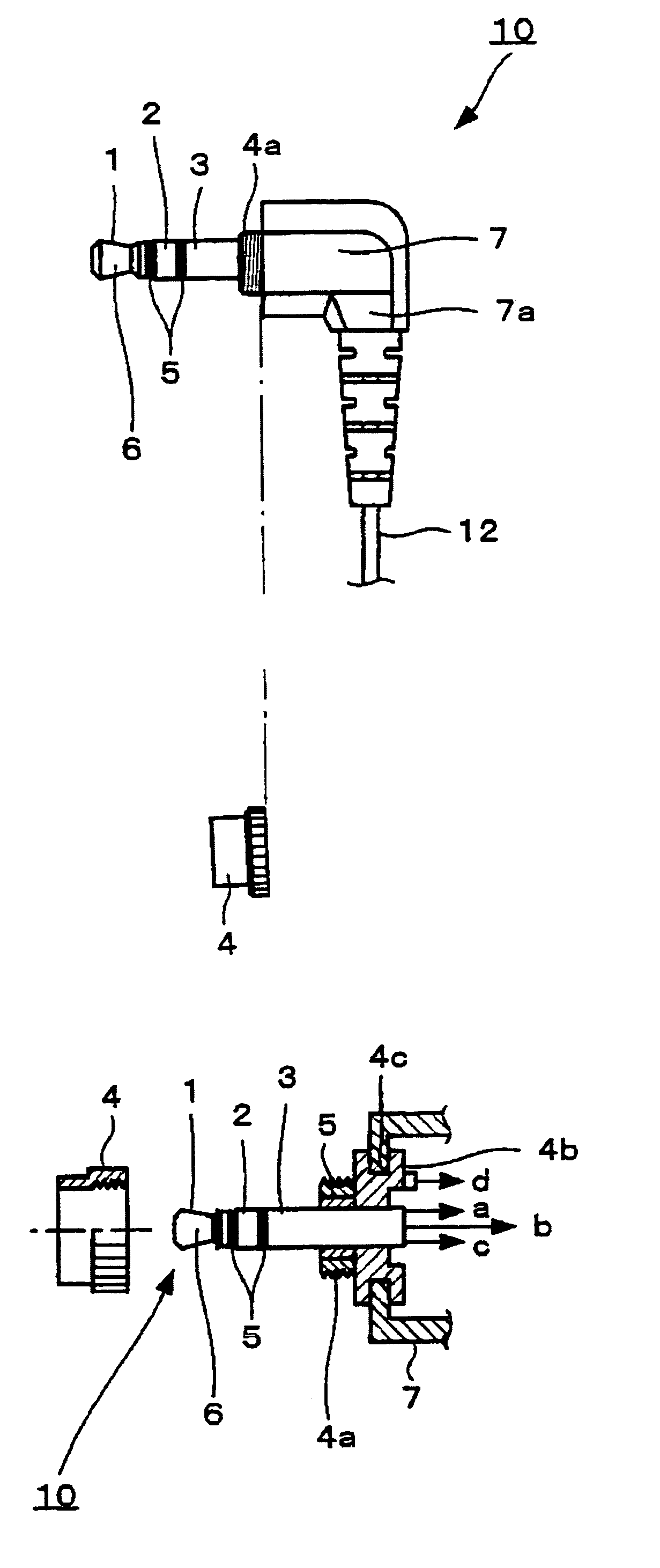
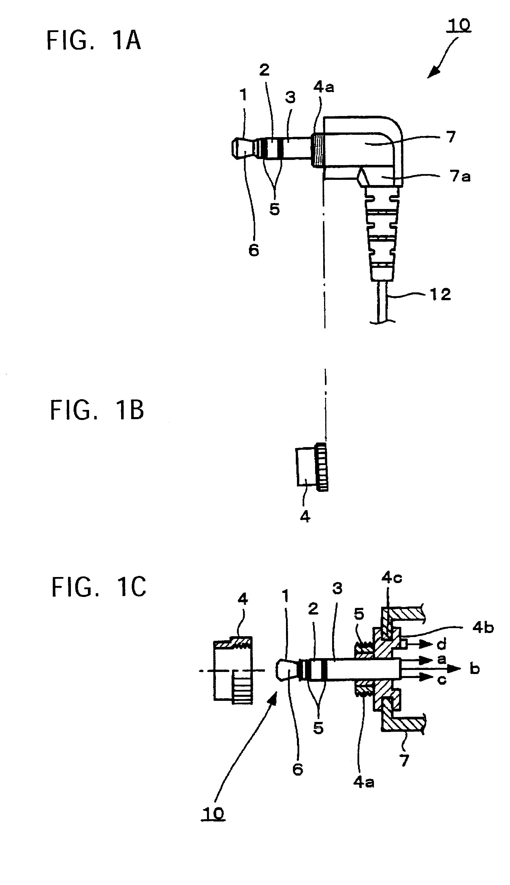
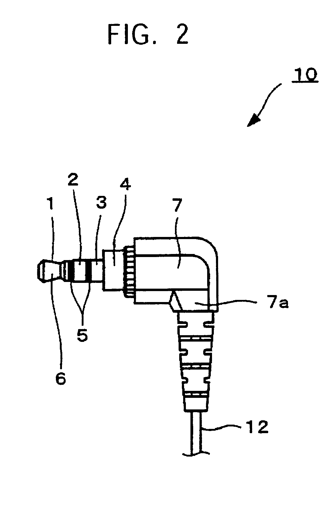
[0034]As a switch-equipped plug according to the present invention, a 3-electrode / 4-electrode shared plug will be described. FIG. 1A is a side view of a 3-electrode / 4-electrode shared plug when used as a 3-electrode plug, according to the present invention, FIG. 2 is a side view of a 3-electrode / 4-electrode shared plug when used as a 4-electrode plug, according to the present invention, FIG. 3 is a circuit diagram of the 3-electrode / 4-electrode shared plug according the present invention, FIG. 4 is a perspective view of a switch-equipped earphone microphone of a portable phone, to which the present invention is applied.

[0035]Before describing the 3-electrode / 4-electrode shared plug according to the present invention, the overall structure of a switch-equipped earphone microphone 22, to which the 3-electrode / 4-electrode shared plug is applied, will be described with reference to FIG. 4.

[0036]As shown in FIG. 4, a 3-electrode / 4-electrode shared plug 10 according to the present inventi...


PUM


Abstract

A switch-equipped input-output plug available for a voice input-output connector (jack) different from one type of portable phone or the like from another is provided. A connecting portion of a 4-electrode plug, for connecting a manipulate-signal electrode has a screwing portion formed therearound. is used for two types of portable phones respectively equipped with 4-electrode and 3 electrode jacks. Thus, a single type of plug is commonly available for two types of portable phones respectively equipped with 4-electrode and 3 electrode jacks by using an adaptor designed to serve as the manipulate-signal electrode such that the adaptor is screwed with the connecting portion and is detached from the connecting portion, respectively.

Description

BACKGROUND OF THE INVENTION[0001]1. Field of the Invention[0002]The present invention relates to a switch-equipped input-output plug, and in particular, it relates to an improvement of a switch-equipped 3-electrode / 4-electrode shared input-output plug.[0003]2. Description of the Related Art[0004]Hitherto, a switch-equipped earphone microphone of a portable phone has an input-output terminal different one carrier from another or one type of portable phone from another. The input-output terminals are generally classified into a 3-electrode jack type having a diameter of 2.5 mm and being available for a 3-electrode plug; and a 4-electrode jack type formed by adding a fourth terminal to the outer surface of the 3-electrode jack type.[0005]The above-described 3-electrode and 4-electrode plugs are disclosed in detail in Japanese Registered Utility Model No. 3036532 (see FIGS. 1 to 4, hereinafter, referred to as Patent Document 1). When such a known 3- or 4-electrode plug is used for a voi...

Claims


Application Information

Patent Timeline
Patent Type & Authority Patents(United States)
IPC IPC(8): H01R13/70
CPCH01R13/70H01R24/30H01R24/58H01R2107/00H01R27/00H01R2105/00
Inventor SHINOHARA, IKUO
Owner SONY CORP
Why Eureka
Try Eureka