Gravity operated locking hinge

a gravity-operated, hinge technology, applied in the field of hinges, can solve the problems of knee joint unlocking, and the user walking with a stiff leg, and achieve the effect of preventing the pivot pin

Inactive Publication Date: 2005-12-27
BANDAGE EN CORSETIND BASKO
View PDF15 Cites 10 Cited by
  • Summary
  • Abstract
  • Description
  • Claims
  • Application Information

AI Technical Summary

Benefits of technology

[0029]According to the invention it is furthermore advantageous that the locking element is constructed as a body for transmitting forces from the second part via the locking element to the first part.
[0030]As a result of this measure, forces which are exerted on the first part are transmitted via the locking element to the second part. In order to prevent the pivot pin of the locking element being subjected to excessive stress as a

Problems solved by technology

Without aids, the knees of such patients would give way when they walk.
A significant disadvantage of a hinge of such simple construction is that the user has to walk with a stiff leg.
A significant disadvantage of the solution according to the said documents is that the knee joint will also be unlocked if stress is exerted on, for example, the front of the user's foot.
As a result of this limitation, the solution according to the abovementioned documents is impractical and, moreover, da

Method used


Image

  • Gravity operated locking hinge
  • Gravity operated locking hinge
  • Gravity operated locking hinge

Examples


Embodiment Construction

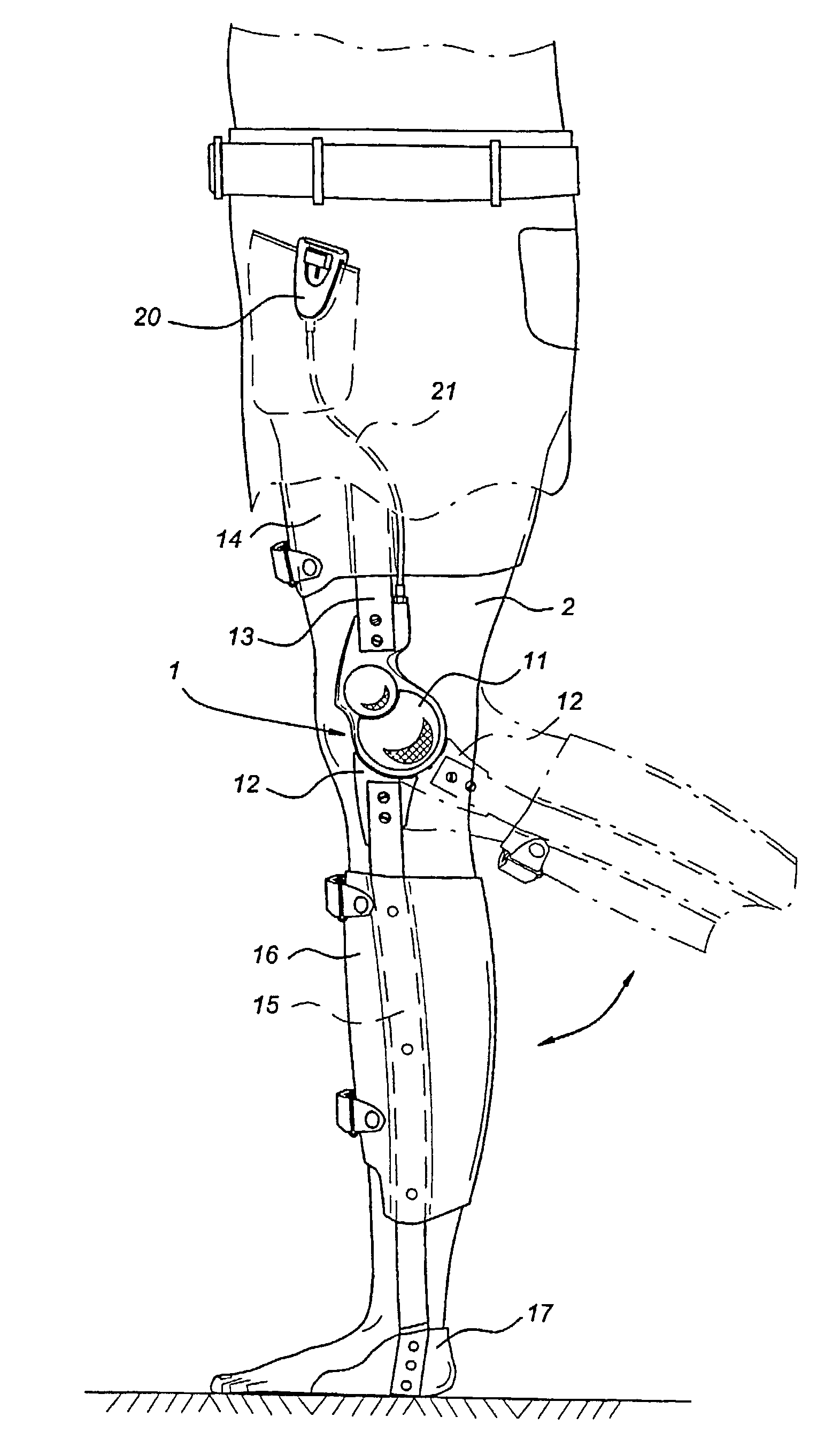
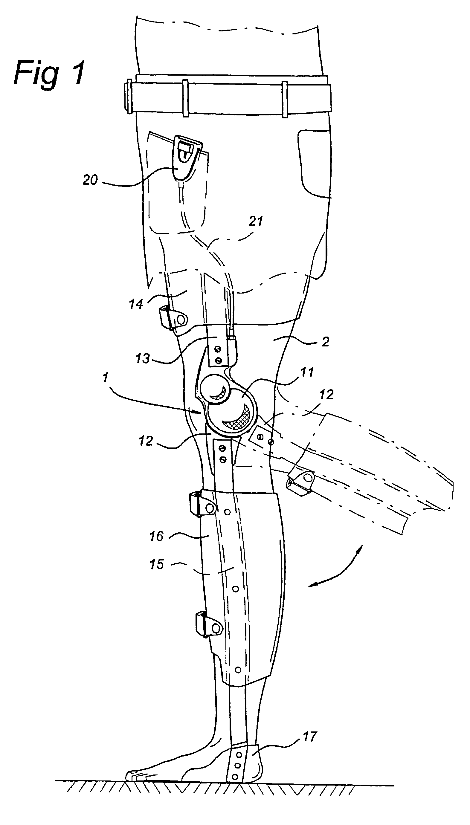
[0051]FIG. 1 shows the hinge 1 that is incorporated in an orthopedic knee joint. The orthopedic knee joint is attached to one leg 2 of a user. The orthopedic knee joint 1 comprises a first part 11 and a second part 12 that are connected to one another such that they can turn. The first part 11 is provided with a bracket 13 on which a fixing element 14 is mounted. Said fixing element 14 is used to attach the orthopedic knee joint to a user's thigh. In the same way, the second part 12 of the hinge 1 is provided with a bracket 15 on which a second fixing element 16 is fixed for attaching the orthopedic knee joint to the user's lower leg. In addition, a support 17, for supporting the user's foot, is fitted at the end of the bracket 15. The hinge 1 can be locked with the aid of a locking element. This is further explained with reference to FIGS. 2 and 3. During the walking movement of a user, this locking element can be moved from a first position for releasing the hinge 1 into a second ...


PUM


Abstract

A hinge provided with a first part and a second part, which parts are able to turn relative to one another from a first position of the hinge into a second position of the hinge, the hinge being provided with a locking element for locking the hinge in the first position thereof, which locking element can move between a first position for releasing the hinge and a second position for locking the hinge. A locking element is fitted in a movable manner for moving under the influence of gravity, between the first position and the second position when the hinge sways.

Description

BACKGROUND OF THE INVENTION[0001]The invention relates to a hinge provided with a first part and a second part, which parts are able to turn relative to one another from a first position of the hinge into a second position of the hinge, the hinge being provided with a locking element for locking the hinge in the first position thereof, which locking element can move between a first position for releasing the hinge and a second position for locking the hinge.[0002]The hinge according to the present invention is in particular suitable as an orthopedic knee joint. Orthopedic knee joints are, for example, used by patients who are not capable of stabilising the knee joint without aids. Without aids, the knees of such patients would give way when they walk. When walking, the leg moves from the point in time that the heel makes contact with the ground from a position in which it is stretched forward into the so-called mid-position stage in which the leg is essentially perpendicular under t...

Claims


Application Information

Patent Timeline
IPC IPC(8): A61F5/01A61F2/64
CPCA61F5/0125A61F2005/0158
Inventor NIJENBANNING, GERTGOUDSMIT, JOSEPHUS ANTON
Owner BANDAGE EN CORSETIND BASKO
Why Eureka
Try Eureka