Eureka AIR delivers breakthrough ideas for toughest innovation challenges, trusted by R&D personnel around the world.

Multifunction keyboard for advanced cursor driven avionic flight decks

a multi-functional keyboard and flight deck technology, applied in the field of aircraft information display systems, can solve the problems of crew abandoning the fms altogether, requiring too much “heads-down” time, and unable to understand text-based techniques, etc., to facilitate the entry and editing of aircraft data, enhance the effect of multi-functional keyboard

Inactive Publication Date: 2005-12-27
HONEYWELL INT INC
View PDF13 Cites 57 Cited by
  • Summary
  • Abstract
  • Description
  • Claims
  • Application Information

AI Technical Summary

Benefits of technology

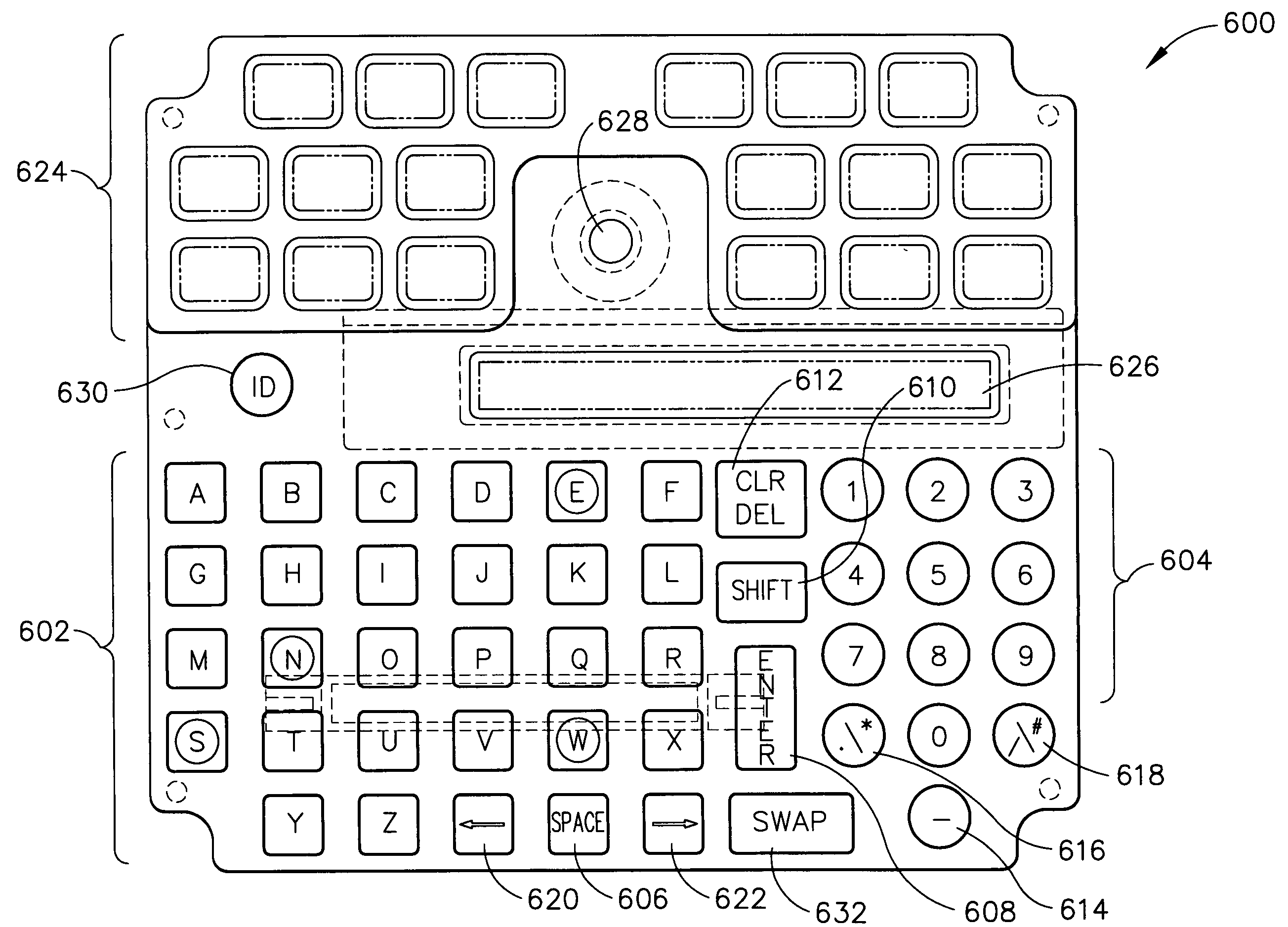
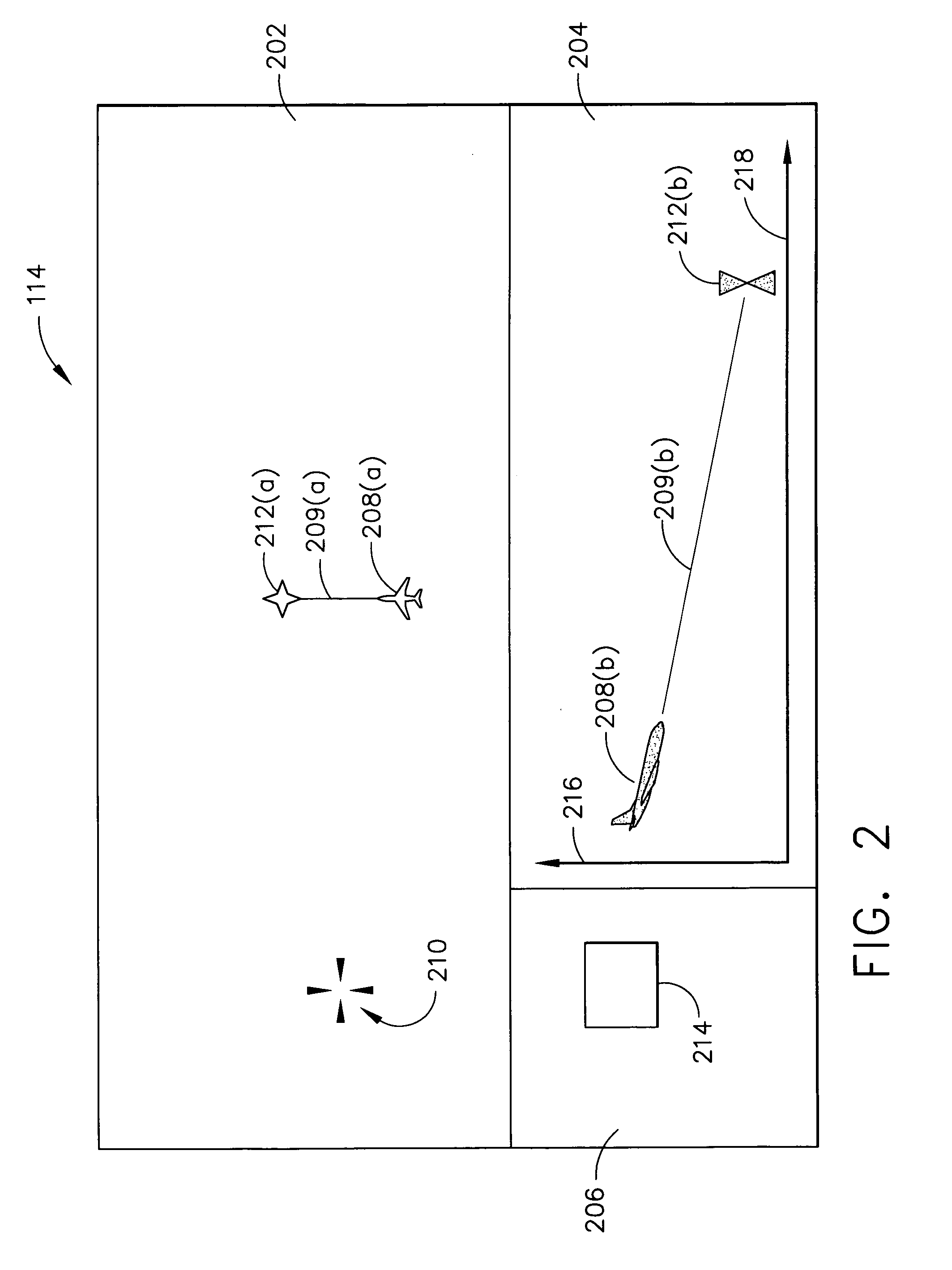
The present invention provides a system and method for a graphical user interface that allows pilots and co-pilots to enter and edit aircraft data using a multifunction keyboard. The interface includes a display that shows various graphical elements associated with the aircraft's operational state, which users can interact with using the keyboard. This allows users to view, modify, or interact with the displayed flight plan and other indicia in real-time, based on the feedback provided by the display. The technical effect of this invention is to provide a more efficient and intuitive way for pilots and co-pilots to access and interact with aircraft data, which can improve operational safety and efficiency.

Problems solved by technology

Although current-generation FMS systems generally have a dedicated controller and display called the MCDU (Multifunction Control Display Unit) or CDU (Control Display Unit), flight plan entry and editing continues to be performed using cumbersome, text-based techniques that have not changed significantly in the last decade.
As a result, flight crews frequently complain that current flight management systems (FMS) are non-intuitive, difficult to interpret, and require too much “heads-down” time.
Indeed, due to the high cockpit workload involved, many flight crews abandon the FMS altogether, choosing instead to fly the aircraft using the autopilot.

Method used


Image

  • Multifunction keyboard for advanced cursor driven avionic flight decks
  • Multifunction keyboard for advanced cursor driven avionic flight decks
  • Multifunction keyboard for advanced cursor driven avionic flight decks

Examples


Embodiment Construction

[0015]Systems and methods in accordance with various aspects of the present invention facilitate one or more users' interaction with an aircraft information display.

[0016]In this regard, the present invention may be described herein in terms of functional block components and various process steps. It should be appreciated that such functional blocks may be realized by any number of hardware, firmware, and / or software components configured to perform the various specified functions. For example, the present invention may employ various integrated circuit components, such as, for example, memory elements, digital signal procession elements, look-up tables, and the like, which may carry out a variety of functions under the control of one or more microprocessors or other control devices. Such general techniques and components that are known to those skilled in the art are not described in detail herein.

[0017]Referring now to FIG. 1, a system in accordance with various aspects of the pr...


PUM


Abstract

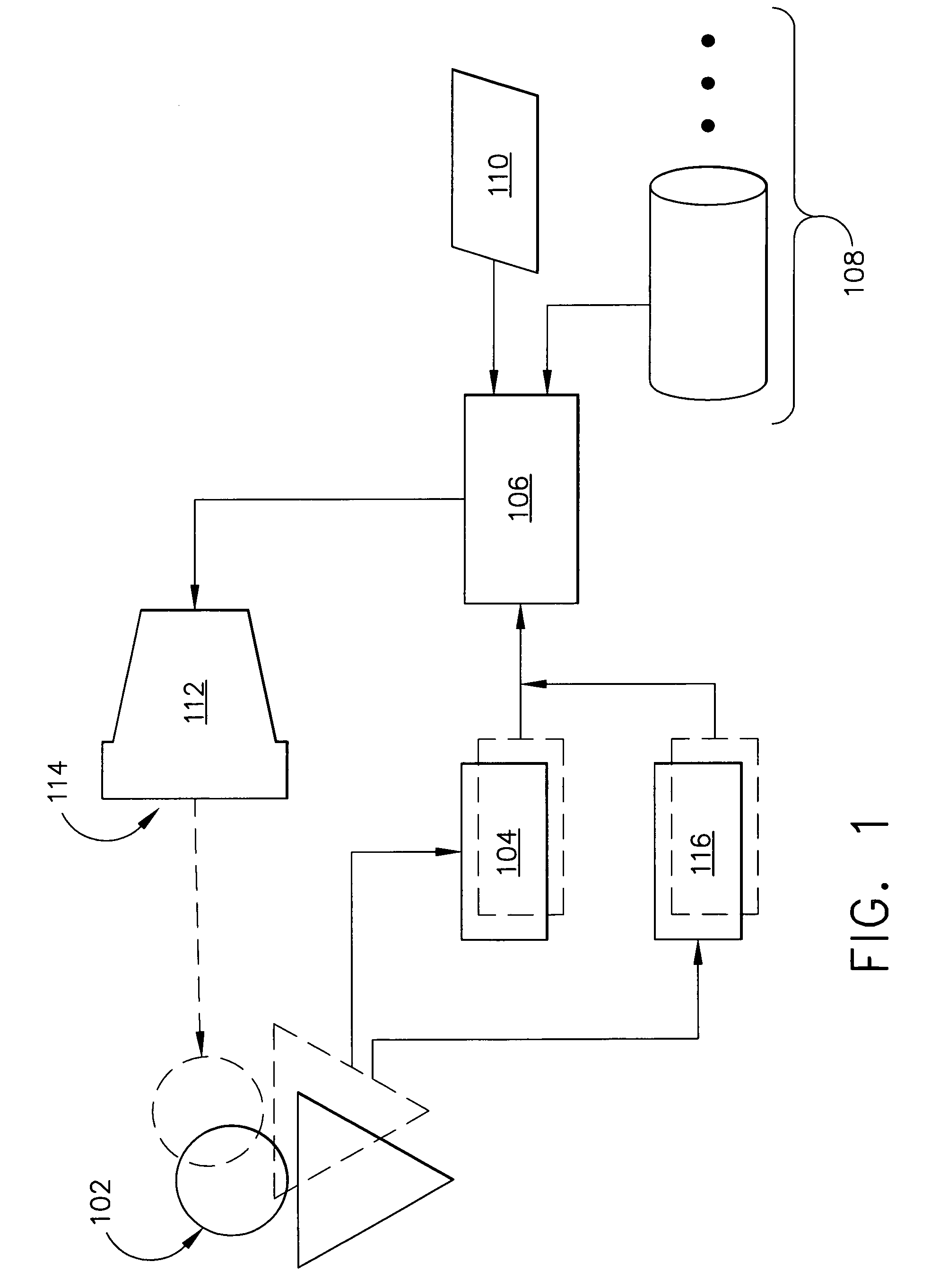
An aircraft display and control system generally includes a processor, a cursor control and selection device, a multifunction keyboard, an aeronautical information database, a geographic database, and a plurality of display devices. Users, such as an aircraft pilot and copilot, can perform flight plan entry and modification by manipulating graphical and textual information on the display devices using the cursor control device and the multifunction keyboard. In one embodiment, the present invention provides an interface to flight deck information systems that is intuitive and easy to use, and which enables flight crew members to easily and effectively enter and modify data displayed by the aircraft flight deck, substantially centralizes avionics controls within one controller, and decreases flight crew “heads-down” time.

Description

REFERENCE TO RELATED APPLICATION[0001]This application claims priority from and the benefit of U.S. Provisional Patent Application Ser. No. 60 / 233,825, filed Sep. 19, 2000, the entire contents of which are hereby incorporated by reference.TECHNICAL FIELD[0002]This invention relates, generally, to data display systems and, more particularly, to a system and method for interaction with an aircraft information display system.BACKGROUND INFORMATION[0003]Aircraft flight displays continue to advance in sophistication, achieving increasingly higher levels of information density and, consequently, presenting a greater amount of visual information to be perceived and understood by the operator. In many applications, it is important that visual displays provide a proper cognitive mapping between what the operator is trying to achieve and the information available to accomplish the task. As a result, such systems increasingly utilize human-factor design principles in order to build instrumenta...

Claims


Application Information

Patent Timeline
Patent Type & Authority Patents(United States)
IPC IPC(8): B64D43/00G01C23/00
CPCB64D43/00G01C23/00
Inventor GYDE, MIKE G.SNYDER, MARK I.STEWART, MICHAEL J.
Owner HONEYWELL INT INC
Why Eureka
Eureka Blog
Learn More