Automatic utterance detector with high noise immunity

a detector and automatic technology, applied in the field of speech recognition, can solve problems such as insufficient reliability of detection under such a noisy situation

Inactive Publication Date: 2005-12-27
INTEL CORP
View PDF13 Cites 12 Cited by
  • Summary
  • Abstract
  • Description
  • Claims
  • Application Information

AI Technical Summary

Problems solved by technology

Obviously, while speech energy gives good results for clean to moderately no...

Method used


Image

  • Automatic utterance detector with high noise immunity
  • Automatic utterance detector with high noise immunity
  • Automatic utterance detector with high noise immunity

Examples


Embodiment Construction

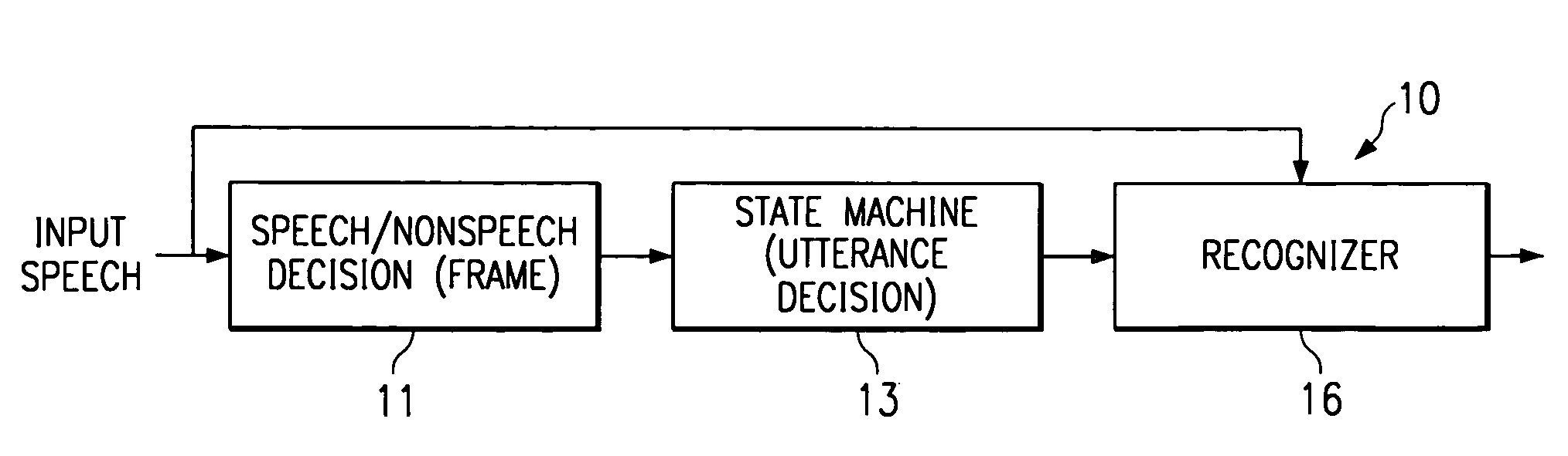
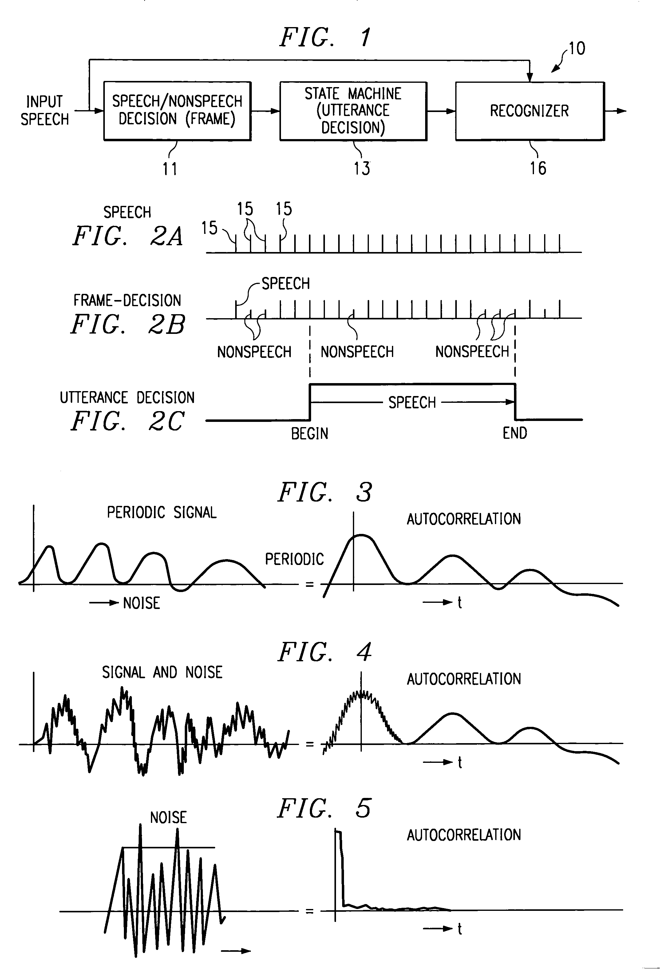
[0022]Referring to FIG. 1, there is illustrated a block diagram of the utterance detector 10 according to one embodiment of the present invention. The detector 10 comprises the first part which is at the frame level detector 11 which determines for each frame if there is speech or non-speech. The second part is an utterance detector 13 that includes a state machine that determines if the utterance is speech. The output of the utterance detector 13 is applied to speech recognizer 16 such that when the utterance detector recognizes speech it enables the recognizer 16 to receive speech and when the detector determines non-speech to turn off or disable the recognizer 16.

[0023]FIG. 2 illustrates the system. Row (a) of FIG. 2 illustrates a series of frames 15. In the first detector 11, it is determined if the frame 15 is speech or non-speech. This is represented by row (b) of FIG. 2. Row (c) of FIG. 2 represents the utterance decision. Detected speech in a frame at frame detector 11 cause...


PUM


Abstract

An utterance detector for speech recognition is described. The detector consists of two components. The first part makes a speech/non-speech decision for each incoming speech frame. The decision is based on a frequency-selective autocorrelation function obtained by speech power spectrum estimation, frequency filter, and inverse Fourier transform. The second component makes utterance detection decision, using a state machine that describes the detection process in terms of the speech/non-speech decision made by the first component.

Description

[0001]This application claims priority under 35 USC § 119(e)(1) of provisional application No. 60 / 161,179, filed Oct. 22, 1999.FIELD OF INVENTION[0002]This invention relates to speech recognition and, more particularly, to an utterance detector with high noise immunity for speech recognition.BACKGROUND OF INVENTION[0003]Typical speech recognizers require an utterance detector to indicate where to start and to stop the recognition of the incoming speech stream. Most utterance detectors use signal energy as basic speech indicator. See, for example, J.-C. Junqua, B. Mak, and B. Reaves, “A robust algorithm for word boundary detection in the presence of noise,”IEEE Trans. on Speech and Audio Processing, 2(3):406–412, July 1994 and L. Lamels, L. Rabiner, A. Rosenberg, and J. Wilpon, “An improved endpoint detector for isolated word recognition,”IEEE ASSP Mag., 29:777–785, 1981.[0004]In applications such as hands-free speech recognition in a car driven on a highway, the signal-to-noise rati...

Claims


Application Information

Patent Timeline
IPC IPC(8): G10L11/02G10L15/20
CPCG10L25/78G10L25/06
Inventor GONG, YIFANKAO, YU-HUNG
Owner INTEL CORP
Why Eureka
Try Eureka