Multiple blade blender apparatus

a blender and blade technology, applied in the field of blenders, can solve the problems of insufficient blending and long blending tim

Inactive Publication Date: 2006-01-03
IDEAL LIVING HLDG
View PDF26 Cites 43 Cited by
  • Summary
  • Abstract
  • Description
  • Claims
  • Application Information

AI Technical Summary

Problems solved by technology

The single blade shaft configuration does not promote sufficient movement in the foods or other materials in the blender and often results in lengthy blending times and inadequate blending.

Method used


Image

  • Multiple blade blender apparatus
  • Multiple blade blender apparatus
  • Multiple blade blender apparatus

Examples


Embodiment Construction

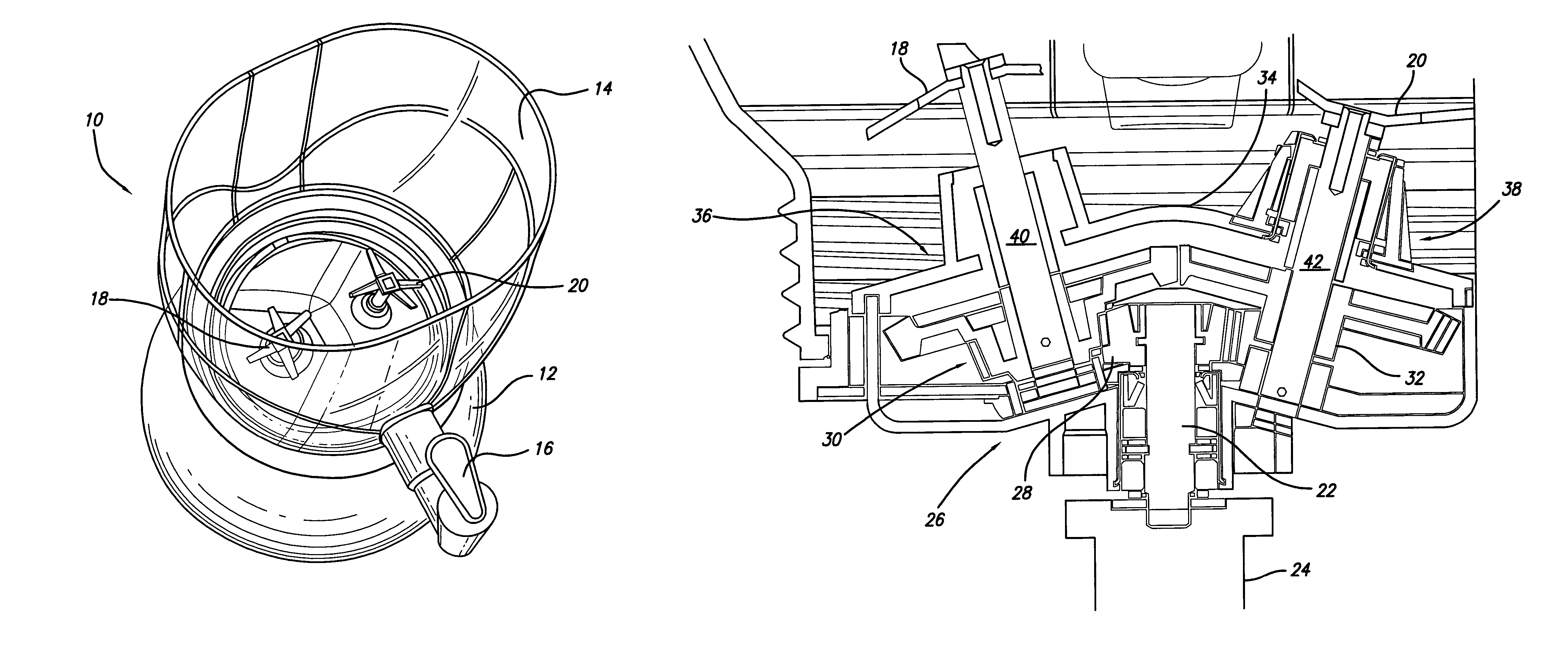
[0005]A multi-blade blender is disclosed having a drive shaft, a gear system, and at least two blade assemblies. Each blade assembly includes a blade affixed to an end of a blade shaft. The blade shafts of the first, second and third blade assemblies are angled from the vertical position toward the container wall. The gear system engages at least one of the blade assemblies. The drive shaft engages the gear system and causes the blade assemblies to rotate in operation.

BRIEF DESCRIPTION OF DRAWINGS

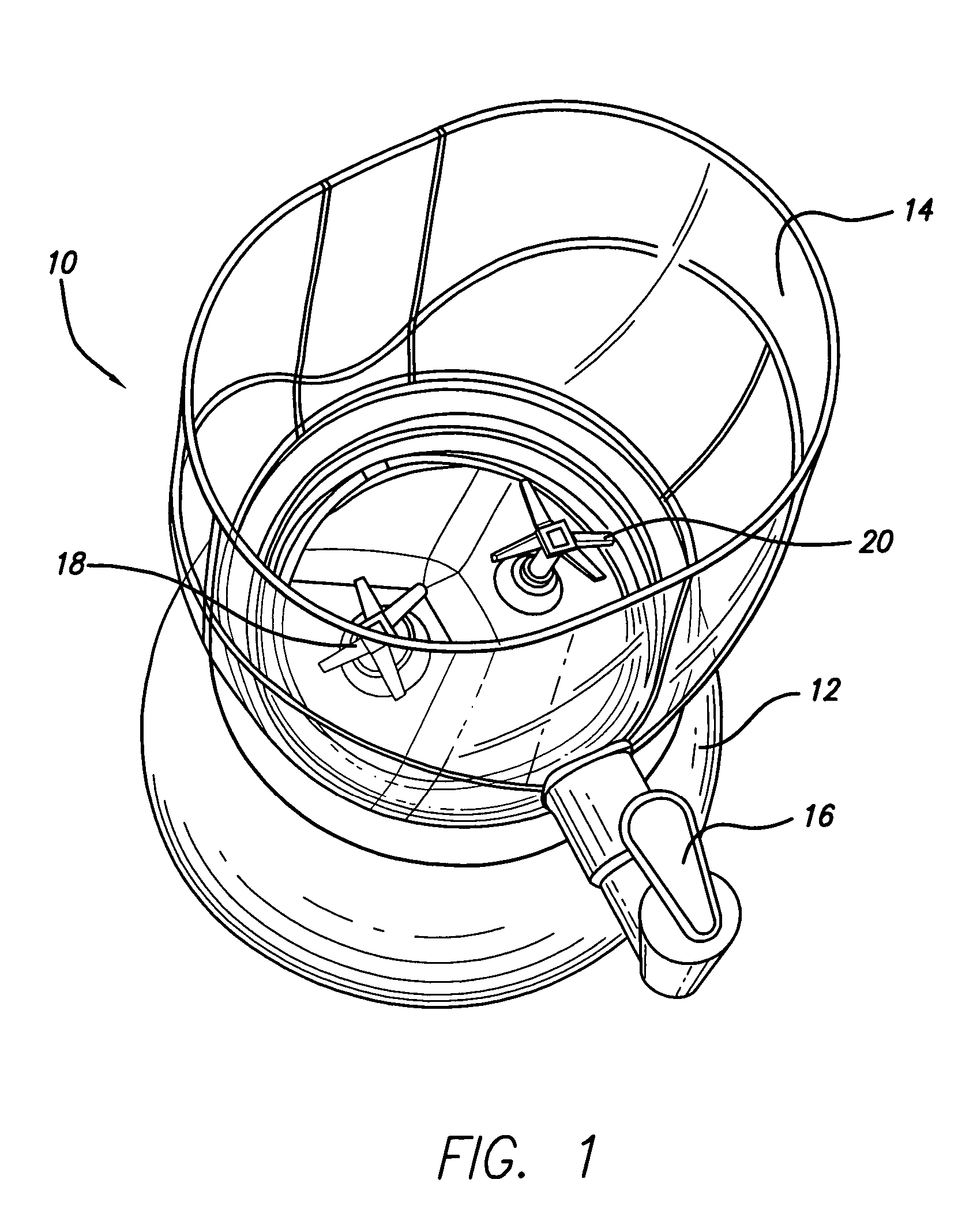
[0006]FIG. 1 is a perspective view of a double blade blender, according to one embodiment of the present invention;

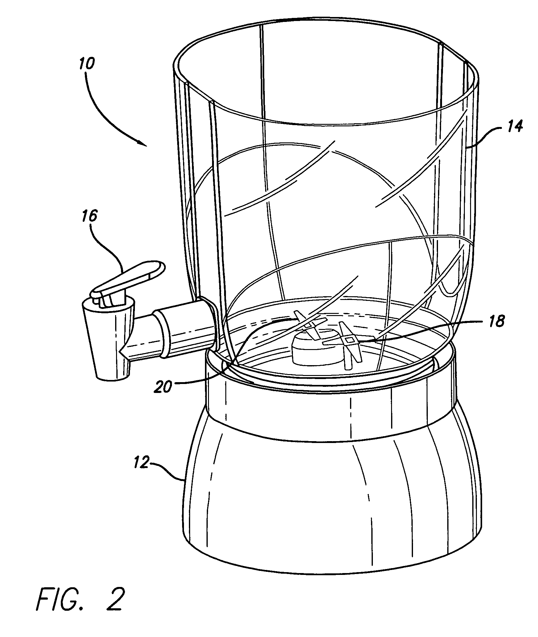
[0007]FIG. 2 is another perspective view of the double blade blender of FIG. 1;

[0008]FIG. 3 is a perspective view of a multiple blade blender, according to another embodiment of the present invention;

[0009]FIG. 4 is a cross-sectional view of the base of a multiple blade blender, according to one embodiment of the present invention;

[0010]FIG. 5 is a perspective view of a double ...


PUM


Abstract

A multi-blade blender is disclosed having a drive shaft, a gear system, and at least two blade assemblies. Each blade assembly includes a blade affixed to an end of a blade shaft. The blade shafts of the first, second and third blade assemblies are angled from the vertical position toward the container wall. The gear system engages at least one of the blade assemblies. The drive shaft engages the gear system and causes the blade assemblies to rotate in operation.

Description

RELATED APPLICATIONS[0001]The present application claims priority from U.S. Provisional Application No. 60 / 490,227, entitled “Double Blade Blender Apparatus,” filed on Jul. 25, 2003 and U.S. Provisional Application No. 60 / 490,152, entitled “Multiple Blade Blender Apparatus,” filed on Jul. 25, 2003.FIELD OF INVENTION[0002]The present invention relates generally to blenders, and more particularly to a blender apparatus utilizing two or more blade assemblies.BACKGROUND OF THE INVENTION[0003]Electric blenders have been in existence for many years. Electric blenders are used to chop, mix, and blend varying foods or other materials such as liquids. Blenders include an electric motor that drives a blade shaft which in turn causes rotational movement of a blade on the end of the blade shaft. This single blade shaft configuration chops and blends food and other materials by processing only those materials that fall to the center of the blender base. The single blade shaft configuration does ...

Claims


Application Information

Patent Timeline
Patent Type & Authority Patents(United States)
IPC IPC(8): B01F7/00A47J43/042A47J43/07A47J43/08
CPCA47J43/042A47J43/085A47J43/0794A47J43/0716
Inventor NIKKAH, ALI
Owner IDEAL LIVING HLDG
Why Eureka
Try Eureka