Cervical prosthesis with insertion instrument

a cervical prosthesis and insertion instrument technology, applied in the field of cervical prosthesis with insertion instrument, can solve the problems of incorrect mounting, not entirely a simple matter to mount the prosthesis parts on the insertion instrument, etc., and achieve the effect of more reliabl

Inactive Publication Date: 2006-01-03
CERVITECH INC
View PDF16 Cites 74 Cited by
  • Summary
  • Abstract
  • Description
  • Claims
  • Application Information

AI Technical Summary

Benefits of technology

[0002]The object of the invention is to make implantation of a cervical prosthesis with an insertion instrument more reliable.
[0005]A holder is also provided which receives the prosthesis with an exact fit. This ensures that the projections and also the recesses on the prosthesis are located at a predetermined position on the holder. On the side corresponding to the anterior face of the prosthesis, the holder is open to permit removal of the prosthesis. It has guide elements by means of which the gripping members of the insertion instrument are guided into a position, relative to the prosthesis, in which the complementary projections and recesses on the prosthesis and on the gripping members lie level with and opposite one another ready to engage. When the operating surgeon, starting from this position, closes the gripping members, the projections and recesses safely engage and the desired, correct mounting of the prosthesis on the insertion instrument is reliably obtained.

Problems solved by technology

However, it is not entirely a simple matter to mount the prosthesis parts on the insertion instrument, because the projections and recesses are very small.
Moreover, it can also easily happen that a mounting which is done incorrectly goes unnoticed.

Method used


Image

  • Cervical prosthesis with insertion instrument
  • Cervical prosthesis with insertion instrument
  • Cervical prosthesis with insertion instrument

Examples


Embodiment Construction

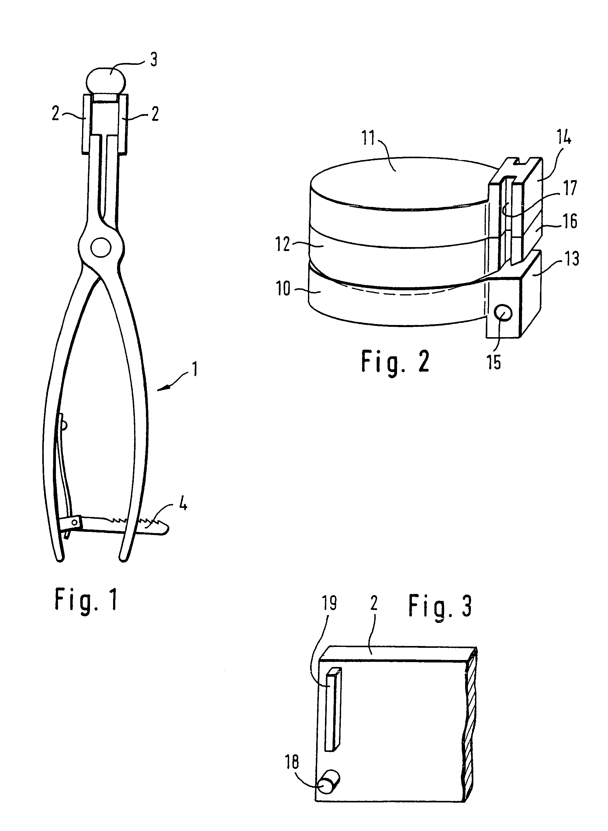
[0014]The insertion instrument 1 is designed as a forceps which, at the front end, has a pair of gripping members 2 which grip the prosthesis 3 from opposite sides. In the example shown, the A-P (anterior-posterior) direction coincides with the longitudinal direction of the insertion instrument. This is preferable. However, the longitudinal direction of the instrument can also deviate slightly from the A-P direction of the prosthesis. In FIG. 2 the dorsal face of the prosthesis is arranged on the left. The forceps can be secured in the closed position by a releasable lock 4.

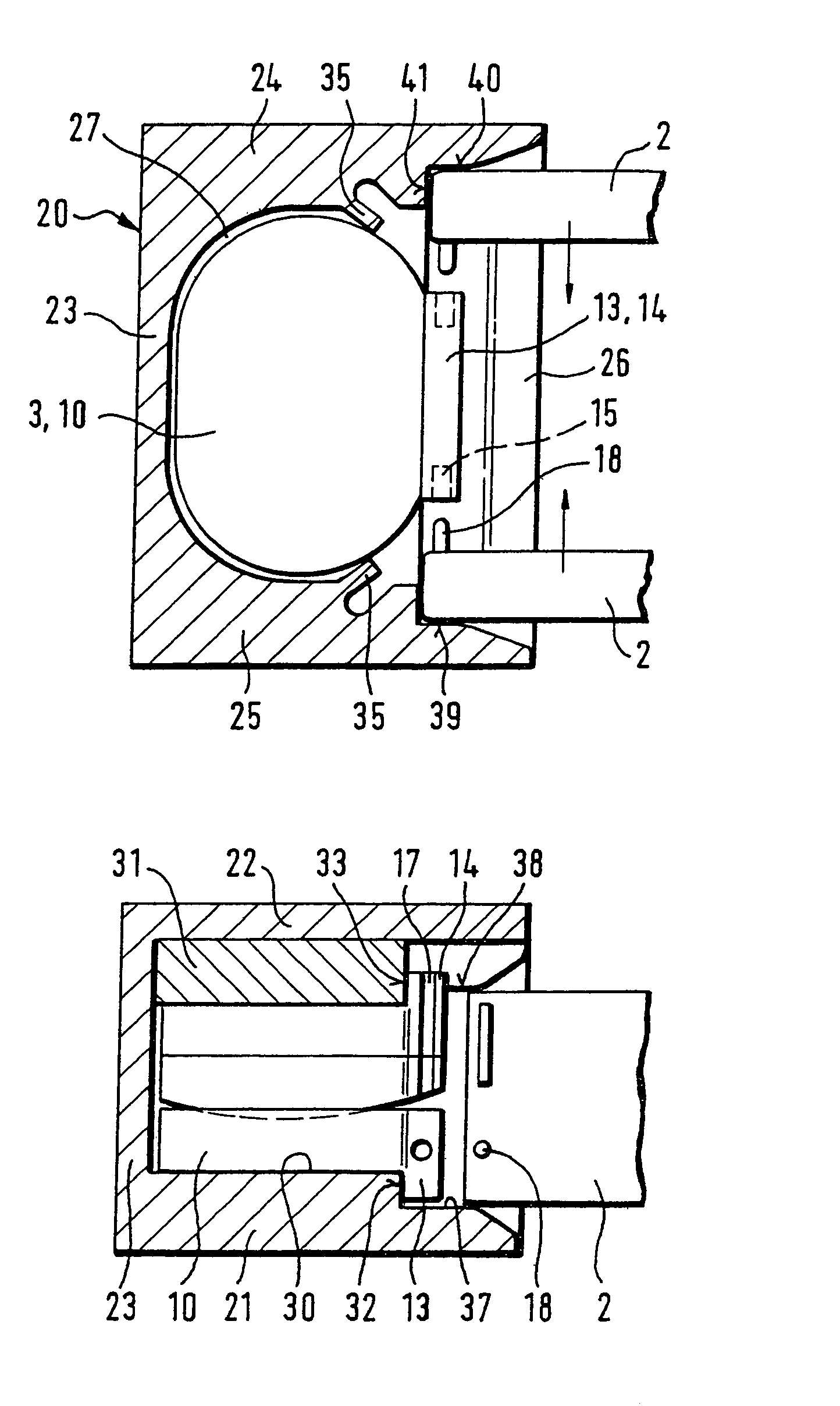
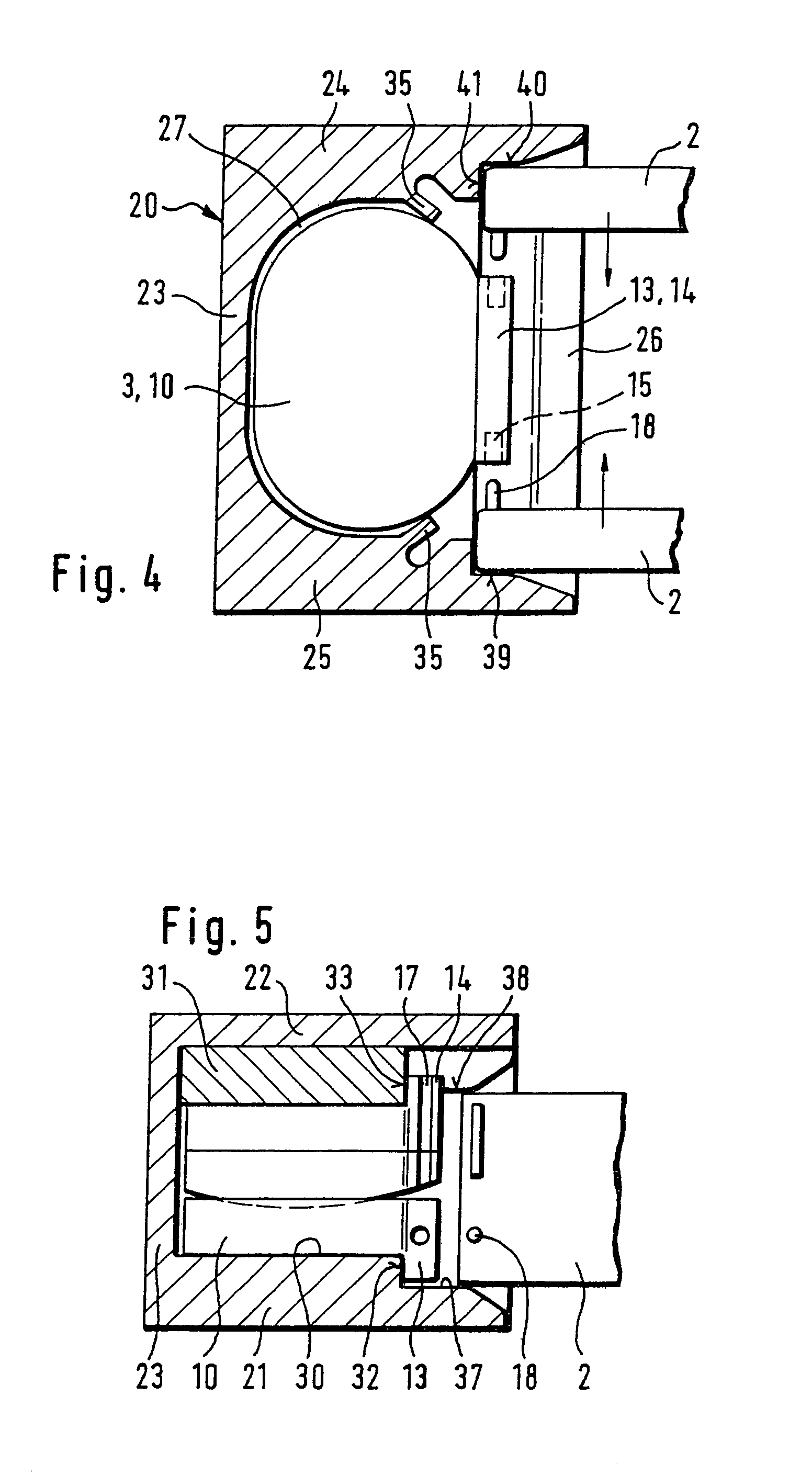
[0015]According to FIG. 2, the prosthesis consists of two cover plates 10, 11 and of a prosthesis core 12 which forms a hinge with the cover plate 10. The height of the prosthesis can be varied, namely by using prosthesis cores 12 of different heights. Along their ventral edge, the cover plates 10, 11 each have a flange 13, 14 which is slightly narrower than the plate-shaped parts of the cover plates 10, 11 and o...


PUM


Abstract

A device for implanting a cervical prosthesis includes a cervical prosthesis, an insertion instrument, and a holder which facilitates the connection of the gripping members of the insertion instrument to the prosthesis. The holder receives the prosthesis with an exact fit and has, on the anterior face of the prosthesis, an opening for admission of the gripping members of the insertion instrument. The opening contains guide elements for guiding the gripping members of the insertion instrument into a removal position in which the complementary projections and recesses of the gripping members and of the prosthesis lie opposite one another.

Description

FIELD AND BACKGROUND OF THE INVENTION[0001]It is known (EP-A 333990) to implant intervertebral prostheses using an insertion instrument with a pair of gripping members which grip the prosthesis on opposite sides. The gripping members connected rigidly to one another each have a groove extending in the A-P direction and receiving the two plate edges which extend in the A-P direction and which are held in said groove by friction or by a spring-mounted catch. When the prosthesis has reached the site in which it is to be implanted, the instrument is removed from it. The plate edges slide in the A-P direction out of the grooves. Gripping members of this kind are suitable only for end plates whose side edges extend parallel to one another and are at a predetermined and always constant distance from one another. They are unsuitable for small prostheses, such as are used in the area of the cervical spine, and for those prostheses which do not have a side edge designed to cooperate with the ...

Claims


Application Information

Patent Timeline
Patent Type & Authority Patents(United States)
IPC IPC(8): A61F2/44A61B17/88A61B17/28A61B17/56A61F2/00A61F2/30A61F2/46
CPCA61F2/0095A61F2/4425A61F2/4611A61F2002/30616A61F2002/30716A61F2250/009A61F2002/30828A61F2002/443A61F2002/4622A61F2002/4628A61F2002/30807A61B17/88A61B17/56
Inventor KELLER, ARNOLD
Owner CERVITECH INC
Why Eureka
Try Eureka