[0010] Thus, the primary object of the present invention is to improve a liquid container having a liquid outlet and an
information storage means of a
contact type, in order to make it easier to
mount or dismount, simpler in the structure of the mechanism for mounting it, more reliable and accurate in terms of its position relative to a device to which it is connected, smaller in the amount of force necessary to
mount it, and also, more reliable in terms of the connection between its liquid outlet and the liquid inlet of a device to which it is connected, and the
electrical connection between its
information storage means and the
information storage means of the device to which it is connected.
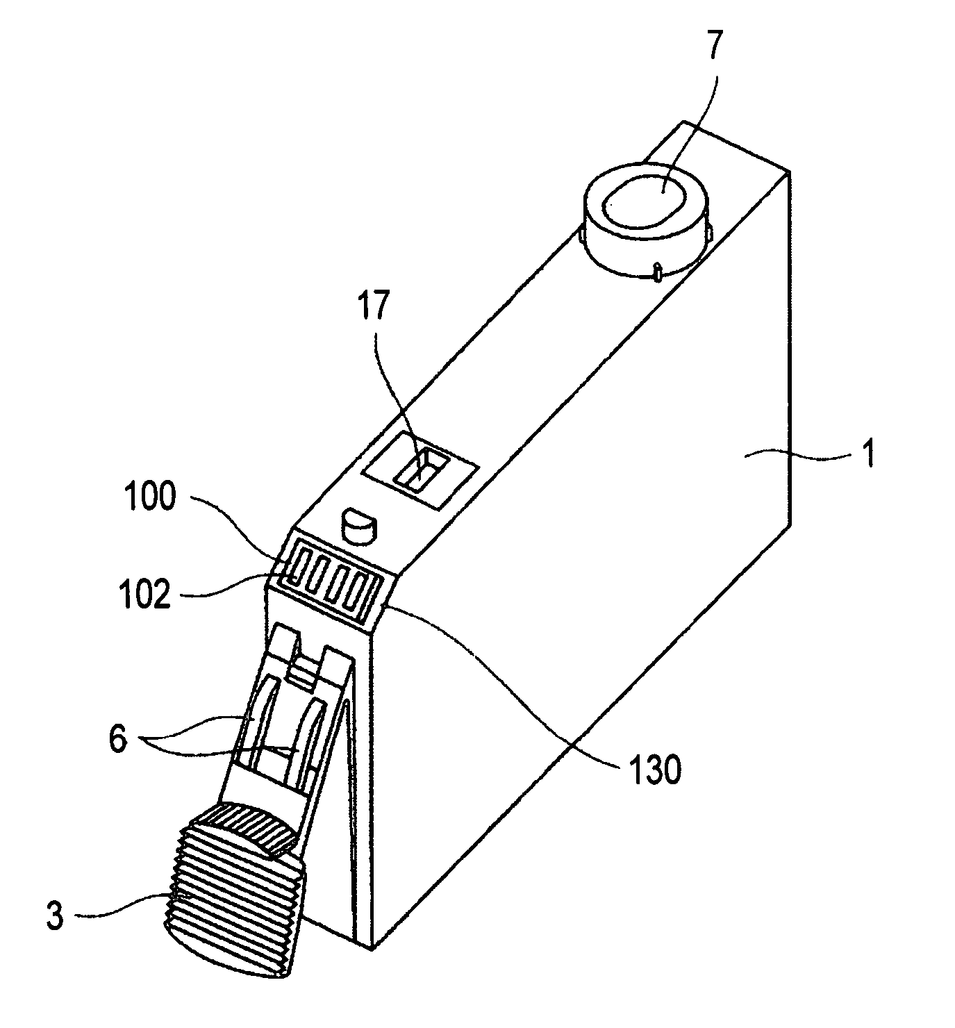
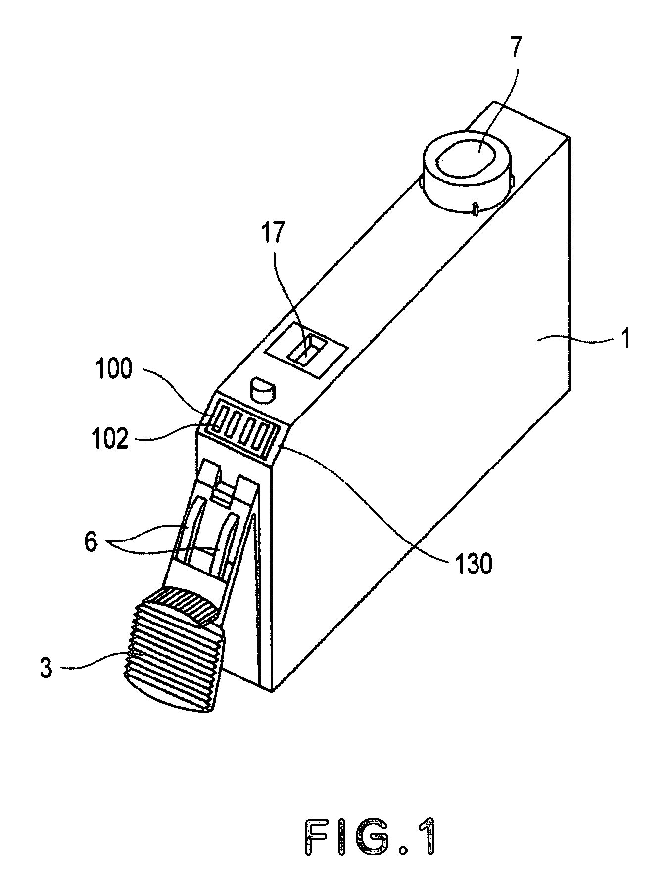
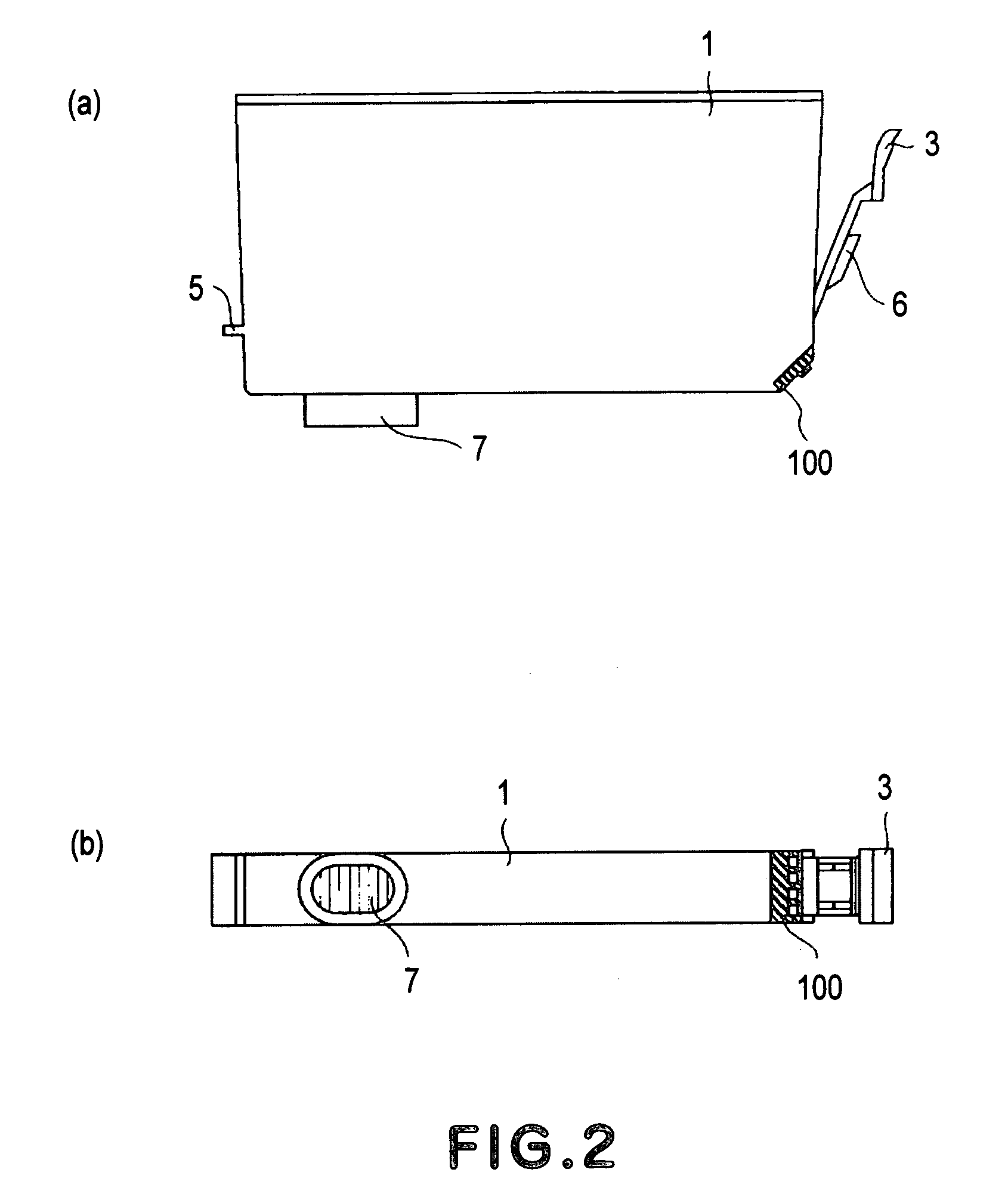
[0013] A liquid container structured described above is mounted, in the following manner, into a predetermined liquid container
mount of a device to which the liquid container is to be attached: First, a liquid container anchoring first portion on the external surface of one of the lateral walls of the liquid container is to be engaged with a liquid container anchoring first portion of the liquid container mount, and the liquid container is to be pressed by its opposite wall from the wall having the liquid outlet. As the liquid container is pressed, the liquid container moves into the liquid container mount while rotating about the liquid container anchoring first portion. It is ensured by the resiliency of the latching lever of the liquid container that the liquid container is accurately positioned relative to the liquid container mount and retained there. Providing the latching lever of the liquid container with a liquid container anchoring second portion engageable with the liquid container anchoring portion of the liquid container mount further ensures that the liquid container is accurately positioned relative to the liquid container mount, and makes it easier to mount the liquid container.
[0014] Further, since the liquid container is accurately and reliably positioned relative to the liquid container holder (mount), and the liquid outlet of the liquid container is positioned between the lateral wall of the liquid container, on the external surface of which the liquid container anchoring portion, which serves as the above described rotational center, is located, and the opposite lateral wall of the ink container, the possibility of liquid leakage is minimized by the synergetic coordination of the force generated by the
contact pressure between the liquid outlet of the liquid container and the liquid inlet of the liquid container mount side, and the force generated by the resiliency of the latching lever of the liquid container.
[0015] In addition, the electrical contacts of the information storage means are disposed on the corner portion, or the edge, between the lateral wall of the liquid container having the liquid outlet and the lateral wall of the liquid container upon which the force generated by the resiliency of the latching lever acts. Therefore, the electrical contacts of the information storage means come into contact with the electrical contacts on the liquid container holder side immediately before the process for mounting the liquid container in the rotational movement is completed. In other words, the electrical contacts of the liquid container and the electrical contacts of the liquid container holder side are placed in contact with each other by the same action taken to couple the liquid outlet of the liquid container with the ink inlet of the liquid container holder. Therefore, not only are the electrical contacts on both sides are placed in contact with each other in the preferable condition, but also, the amount of force required to mount the liquid container is substantially smaller compared to that required when the liquid container in accordance with the prior art is mounted. Further, the latching lever (supporting member) is structured so that its surface facing the wall of the liquid container holder is tilted in such a manner that the closer a given point of the surface is to the wall of the liquid container having the liquid outlet, the closer the given point of the surface is to the wall of the liquid container having the latching lever, and the liquid container and the liquid container holder are structured so that as the liquid container is mounted into the liquid container holder, the rotational movement of the liquid container about the liquid container anchoring first portion can be utilized as the lever action, in which the liquid outlet is the point of action. Therefore, if the liquid container is released before the liquid container anchoring second portion of the latching lever completely engages with the liquid container anchoring second portion of the liquid container mount (holder), the liquid container is popped upward by the reaction force, informing therefore an operator of the incompletion of the liquid container mounting process, ensuring thereby that the liquid container is completely mounted. Further, the information storage means is disposed on the aforementioned slanted wall, that is, the corner portion, of the liquid container. Therefore, as the liquid container is mounted into the liquid container mount (holder), the information storage means is positioned at a level which is a step higher than the bottom wall, that is, the wall having the liquid outlet, of the liquid container. Therefore, even if liquid leaks through the liquid outlet, the information storage means would be protected from the effects of the leak.
[0016] As described above, the present invention makes it possible to make a liquid container, which has a liquid outlet and an information storage means having electrical contacts, simpler in the mechanism for mounting it into the liquid container mount of a device to which it is attached, simpler in the procedure for mounting it, more reliable and accurate in positioning, smaller in the amount of force necessary to mount it, and better in the state of connection between its liquid outlet and the liquid inlet of a device to which it is attached and the state of contact between the electrical contacts of its information storage means and the electrical contacts of the device to which it is attached.
[0017] Further, the present invention can structure a combination of a liquid container and the liquid container mount of a device to which the liquid container is to be attached, so that its electrical contacts are protected from the liquid leakage from the liquid container.

