
Ink-jet head and ink-jet printer having ink-jet head

a technology of inkjet printer and inkjet head, which is applied in the direction of printing and inking apparatus, etc., can solve the problems of restricting the width and achieve the effect of smooth ink supply, large width of each common ink passage, and low resistance of the common ink passage to ink

Inactive Publication Date: 2006-01-10
BROTHER KOGYO KK
View PDF14 Cites 15 Cited by
  • Summary
  • Abstract
  • Description
  • Claims
  • Application Information

AI Technical Summary

Benefits of technology

[0008]The invention thus provides an ink-jet head which maintains the smoothness of the ink supply and provides an ink-jet printer having the ink-jet head.
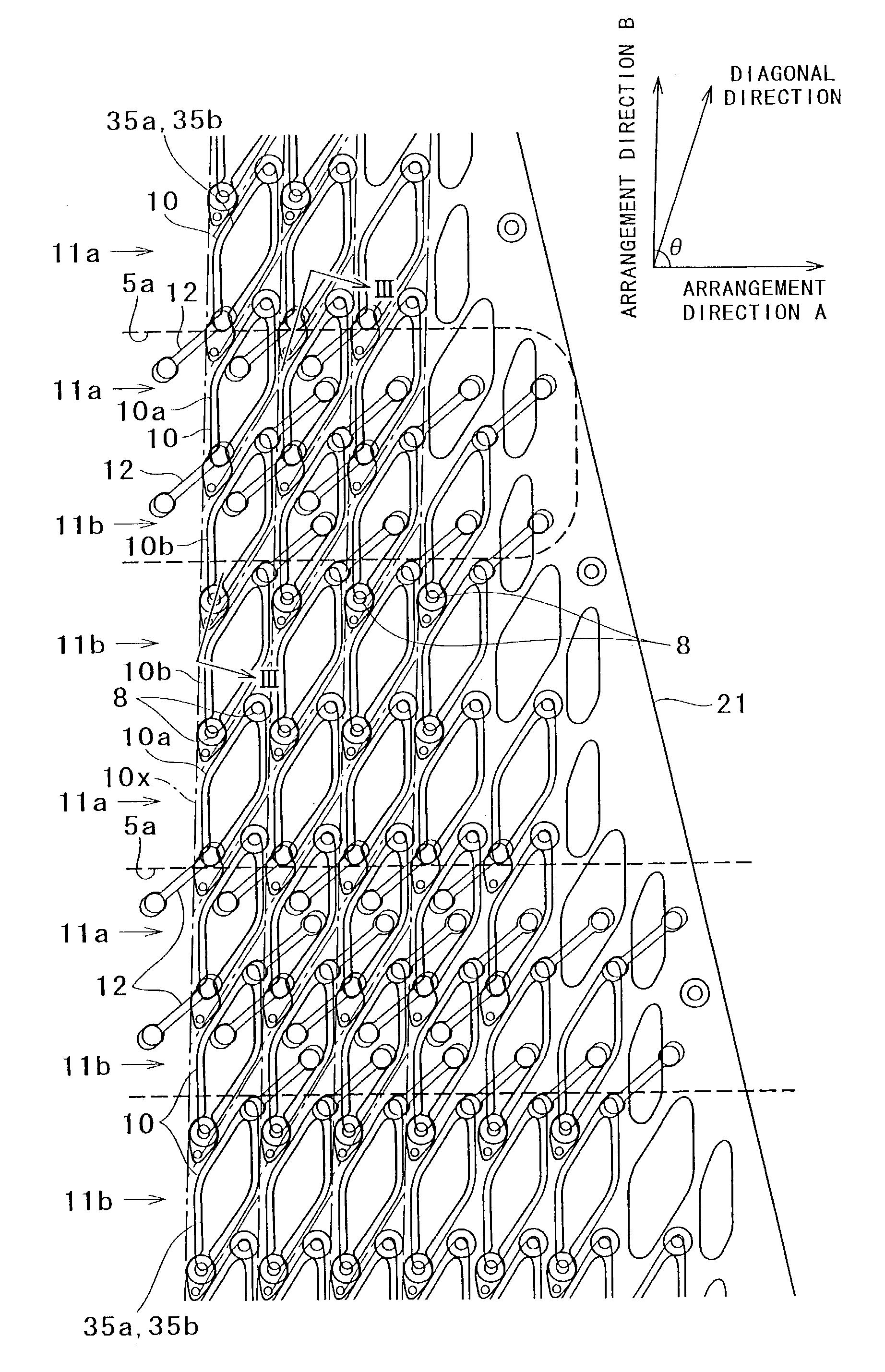
[0011]In this construction, since each nozzle is not disposed at the center of the corresponding pressure chamber but deviated to one side of the pressure chamber, when viewed from the third direction perpendicular to the surface, and each common ink passage is disposed so as to include the boundary region between the first and second pressure chamber rows in which nozzles are deviated to opposite sides to each other with respect to the first direction, the width of each common ink passage can be made large. Therefore, even when the thickness (depth) of each common ink passage in the above third direction is fixed, the passage resistance of the common ink passage to ink is low and smooth ink supply to each pressure chamber can be performed.

Problems solved by technology

Besides, in this case, if nozzles are arranged at a high density to meet the demands of high-resolution and high-speed printing, the arrangement may restrict the width of the common ink passage.

Method used


Image

  • Ink-jet head and ink-jet printer having ink-jet head
  • Ink-jet head and ink-jet printer having ink-jet head
  • Ink-jet head and ink-jet printer having ink-jet head

Examples


Embodiment Construction

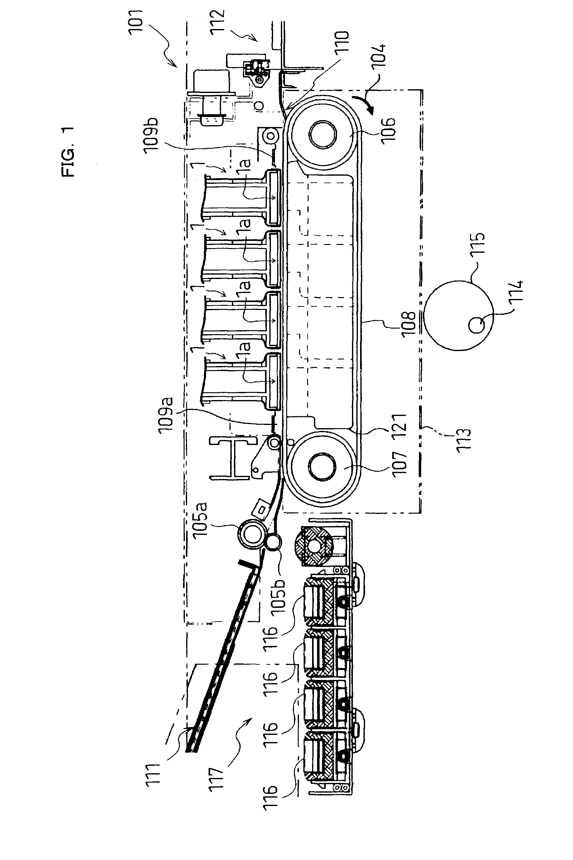
[0025]FIG. 1 is a general view of an ink-jet printer including ink-jet heads according to an embodiment of the invention. The ink-jet printer 101, as illustrated in FIG. 1, is a color ink-jet printer having four ink-jet heads 1. In this printer 101, a paper feed unit 111 and a paper discharge unit 112 are disposed in left and right portions of FIG. 1, respectively.

[0026]In the printer 101, a paper transfer path is provided extending from the paper feed unit 111 to the paper discharge unit 112. A pair of feed rollers 105a and 105b is disposed immediately downstream of the paper feed unit 111 for pinching and putting forward a paper as an image record medium. By the pair of feed rollers 105a and 105b, the paper is transferred from the left to the right in FIG. 1. In the middle of the paper transfer path, two belt rollers 106 and 107 and an endless transfer belt 108 are disposed. The transfer belt 108 is wound on the belt rollers 106 and 107 to extend between them. The outer face, i.e....


PUM


Abstract

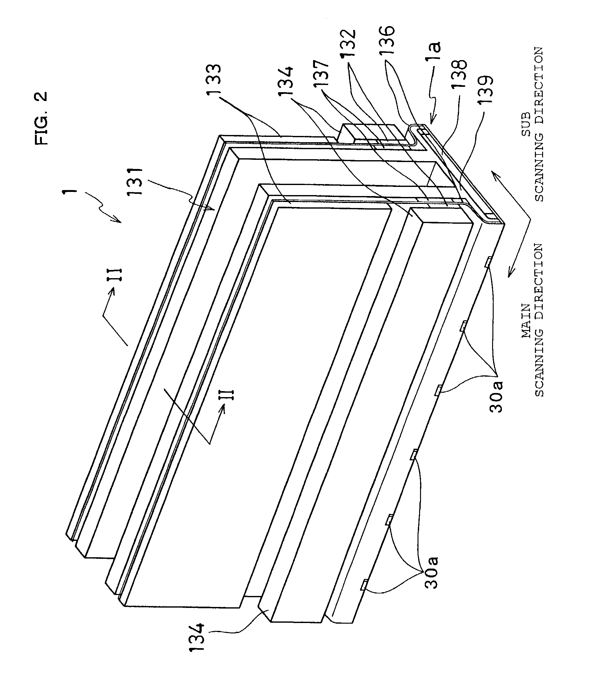
An ink-jet head includes a passage unit including a plurality of pressure chambers each connected with a nozzle and arranged in a matrix in a plane to form a plurality of pressure chamber rows in a first direction in the plane, and a plurality of common ink passages each extending along the first direction and communicating with the pressure chambers.

Description

CROSS-REFERENCE TO RELATED APPLICATION[0001]This application is a Continuation-in-Part of Application No. 10 / 305,979 filed on Nov. 29, 2002, the disclosure of which is incorporated herein in its entirety by reference.BACKGROUND OF THE INVENTION[0002]1. Field of Invention[0003]The invention relates to an ink-jet head for printing by ejecting ink onto a record medium, and to an ink-jet printer having the ink-jet head.[0004]2. Description of Related Art[0005]In an ink-jet printer, an ink-jet head distributes ink, which is supplied from an ink tank, to pulse pressure chambers. The ink-jet head selectively applies pressure to each pressure chamber to eject ink through a nozzle connected with each pressure chamber. As a means for selectively applying pulse pressure to the pressure chambers, an actuator unit or the like may be used in which ceramic piezoelectric sheets are laminated. The printing operations are carried out while reciprocating such a head at a high speed in the widthwise di...

Claims


Application Information

Patent Timeline
Patent Type & Authority Patents(United States)
IPC IPC(8): B41J2/045B41J2/14B41J2/145B41J2/155
CPCB41J2/14209B41J2/145B41J2/155B41J2002/14217B41J2202/20B41J2002/14306B41J2002/14459B41J2002/14491B41J2202/11B41J2002/14225
Inventor SAKAIDA, ATSUOWATANABE, HIDETOSHIHIROTA, ATSUSHI
Owner BROTHER KOGYO KK
Learn More