Exercise apparatus
a technology of exercise equipment and exercise seat, which is applied in the field of exercise equipment, can solve the problems of user's inability to use the conventional exercise equipment while sitting on the chair or lying down, and the structure of the conventional exercise equipment, and achieves the effect of not being able to provide other effects, and being unable to provide other effects
- Summary
- Abstract
- Description
- Claims
- Application Information
AI Technical Summary
Benefits of technology
Problems solved by technology
Method used
Image
Examples
first embodiment
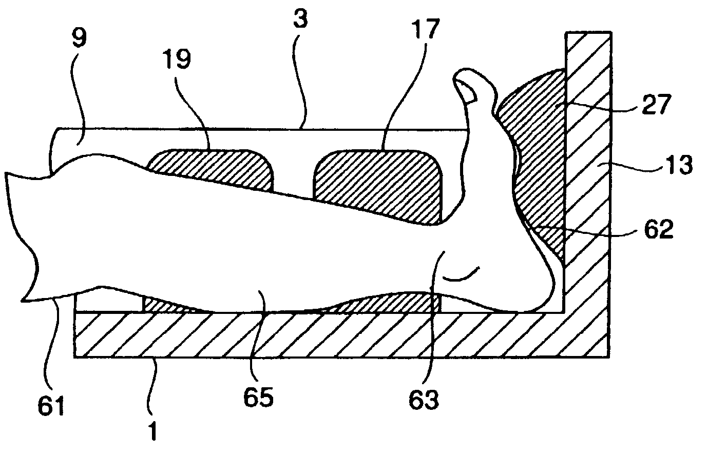
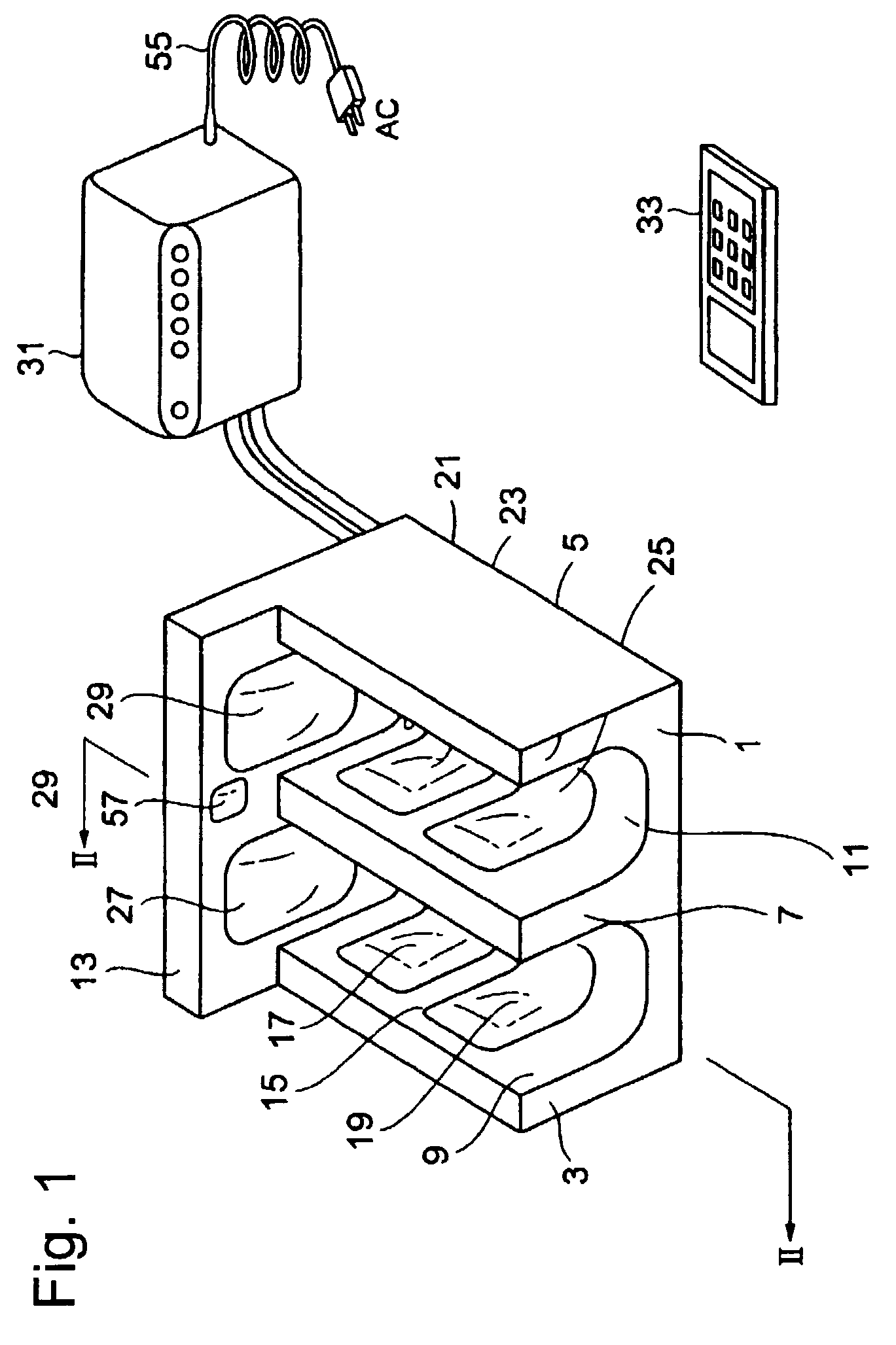
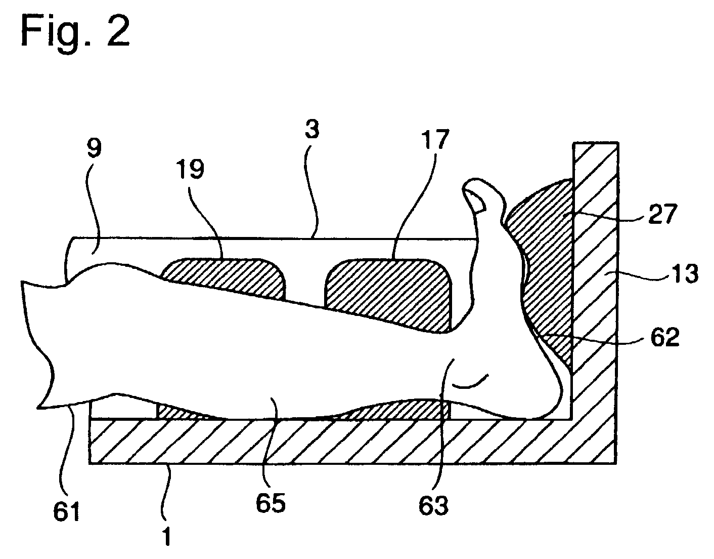
[0037]The exercise apparatus in the present invention will be explained below with reference to FIGS. 1–3. FIG. 1 is a perspective view of the entire structure of the exercise apparatus of the present invention and FIG. 2 is a cross sectional view of the exercise apparatus. The exercise apparatus is generally configured by a portable frame 1 and a controller box 31. The portable frame 1 can be carried around anywhere and is comprised of a left side wall 3, a right side wall 5, and a partition wall 7. The left leg receiving unit 9 is formed between the left side wall 3 and the partition wall 7, and similarly, a right leg receiving unit 11 is formed between the right side wall 5 and the partition wall 7. The frame 1 further includes a sole support wall 13 to contact both left and right soles of the user.
[0038]A leg supporting means 15 is provided within the left leg receiving unit 9. The leg supporting means 15 is comprised of a pair of ankle stabilizing air bags 17 and a pair of calf...
second embodiment
[0053]The exercise apparatus in the present invention will be explained with reference to FIGS. 4A and 4B. In FIG. 4A, the sole support wall 13 is attached to the frame 1 through a hinge 71 in a rotational manner. Further, the sole support wall 13 has a bolt 73 inserted therethrough, where the end of that bolt 73 is tightened to a nut 75 provided on the inner side of the frame 1 such as on the partition wall 7. A spring 77 is attached to the rotation shaft of the hinge 71 of the sole support wall 13 in a manner to bias the sole support wall 13 in a clockwise direction.
[0054]According to the above structure of the exercise apparatus in the second embodiment, when the bolt 73 is screwed into the nut 75, the sole support wall 13 will move against the spring force of spring 77. Thus, the sole support wall 13 rotates in a counterclockwise direction by a rotating angle (vertical angle) α° as shown in FIGS. 4A and 4B. This will increase the pressure applied to the soles 62. The rotating an...
third embodiment
[0060]According to the above structure, as shown in FIG. 6A, a range of movement of the sole, i.e., an angle β° is substantially increased from the example using only one air bag shown in FIG. 6B having the angle of α°. Thus, in the third embodiment, the range of pressing the sole is remarkably increased from the angle α° (FIG. 6B) to the angle β° (FIG. 6A), thereby further increasing the stretch effects.
[0061]Although the diagrams show the air bags pressing against only one sole, the same structure is also used for the other sole as well. Thus, the both soles receive additional pressure and angle for stretching the Achilles tendons. In the example of FIGS. 5 and 6A, although two air bags are piled together, three or more air bags can also be used to increase the stretch effects.
[0062]As in the foregoing, in the third embodiment, the range of pressing the sole is further increased, which allows the exercise apparatus to accommodate various needs and conditions of users. Also, the ex...
PUM
 Abstract
Description
Claims
Application Information
 - R&D
- Intellectual Property
- Life Sciences
- Materials
- Tech Scout
- Unparalleled Data Quality
- Higher Quality Content
- 60% Fewer Hallucinations
Browse by: Latest US Patents, China's latest patents, Technical Efficacy Thesaurus, Application Domain, Technology Topic, Popular Technical Reports.
© 2025 PatSnap. All rights reserved.Legal|Privacy policy|Modern Slavery Act Transparency Statement|Sitemap|About US| Contact US: help@patsnap.com


