
Camera calibration device and method, and computer system

a calibration method and camera technology, applied in the field of camera calibration methods and devices, can solve the problems of no established calibration method, no accurate stereography depth measurement, and inability to obtain an accurate projected image from the front image, etc., and achieve the effect of simplifying calibration

Inactive Publication Date: 2006-01-10
SONY CORP
View PDF12 Cites 85 Cited by
  • Summary
  • Abstract
  • Description
  • Claims
  • Application Information

AI Technical Summary

Benefits of technology

[0022]It is, therefore, an object of the present invention to provide a superior camera calibration method and device capable of calculating parameters representing characteristics of cameras.
[0023]Another object of the present invention is to provide a superior camera calibration method and device adapted for simply carrying out camera calibration in a stereo system by the mere shooting of a known planar pattern with cameras from different directions without any positional restriction on the plane.
[0034]This storage medium defines the structural or functional cooperative relationship between predetermined computer software and the storage medium for realizing the function of the predetermined computer software on a computer system. In other words, the cooperative action is exerted on the computer system by installing desired computer software in the computer system via the storage medium relative to the third embodiment of the present invention, hence achieving the same effects as those attained in the camera calibration device and method relative to the first and second embodiments of the present invention.
[0036]According to the camera calibration device and method of the present invention, simplified camera calibration can be achieved in stereography by the use of an arbitrary plane where no spatial positional restriction is existent. Consequently, an exclusive appliance is not required due to no restriction with regard to the positional relation of the shot plane.
[0039]Shooting the pattern is performed merely to obtain three images of the shot plane while moving the plane (such as plate) where the pattern is drawn (or attached) or moving the camera to pick up images, hence eliminating any great limitation relative to the shot object (data) and consequently achieving simplified calibration.

Problems solved by technology

Therefore, unless calculating the parameter peculiar to the camera and correcting the image data in accordance with such parameter in projective transformation, it is impossible to obtain an accurate projected image from the front image and, consequently, accurate measurement of the depth fails to be carried out by stereography.
Generally, a method of calculating the camera parameters is termed “camera calibration.” Although a variety of techniques for camera calibration have been proposed heretofore, there is no established one in the present circumstances.
In general, some exclusive appliances and so forth are required due to restriction of data for calibration, thus rendering the processing very complicated.

Method used


Image

  • Camera calibration device and method, and computer system
  • Camera calibration device and method, and computer system
  • Camera calibration device and method, and computer system

Examples


Embodiment Construction

[0050]Prior to describing some preferred embodiments of the present invention, an explanation will be given on camera parameters used in this specification and also on a method of distance measurement carried out on the basis of such parameters.

[0051]In the following description, a point on an image is expressed as

m=[u,v]T

[0052]Similarly, a point in space is expressed as

M=[x,y,z]T

[0053]And the points in homogeneous coordinates are expressed respectively as

{tilde over (m)}=[u,v,l]T

{tilde over (M)}=[x,y,z,l]T

[0054]In this case, the relationship between the space point M and the image point m is represented by an equation given below. s⁢⁢m~=⁢A·[R,t]·M~=⁢p·M~(1)

[0055]In the above equation, s denotes a scale factor, and a matrix [R,t] is termed an external parameter which signifies the position of a camera in space. R and t denote, respectively, a rotation matrix and a translation matrix of the image. And a matrix A is termed an internal parameter of a camera expressed by the following e...


PUM


Abstract

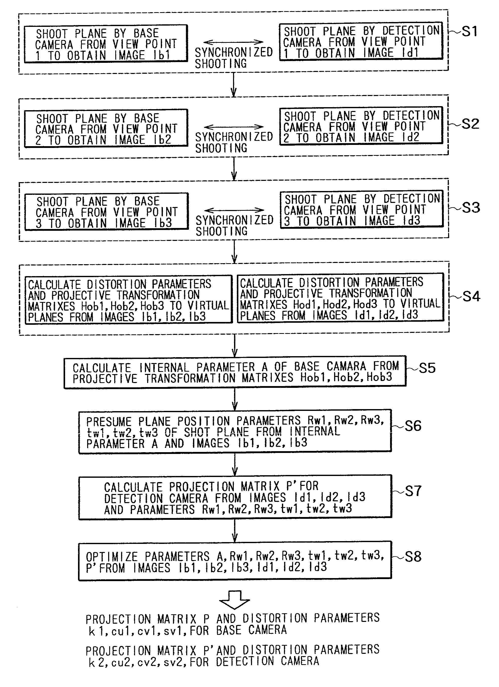
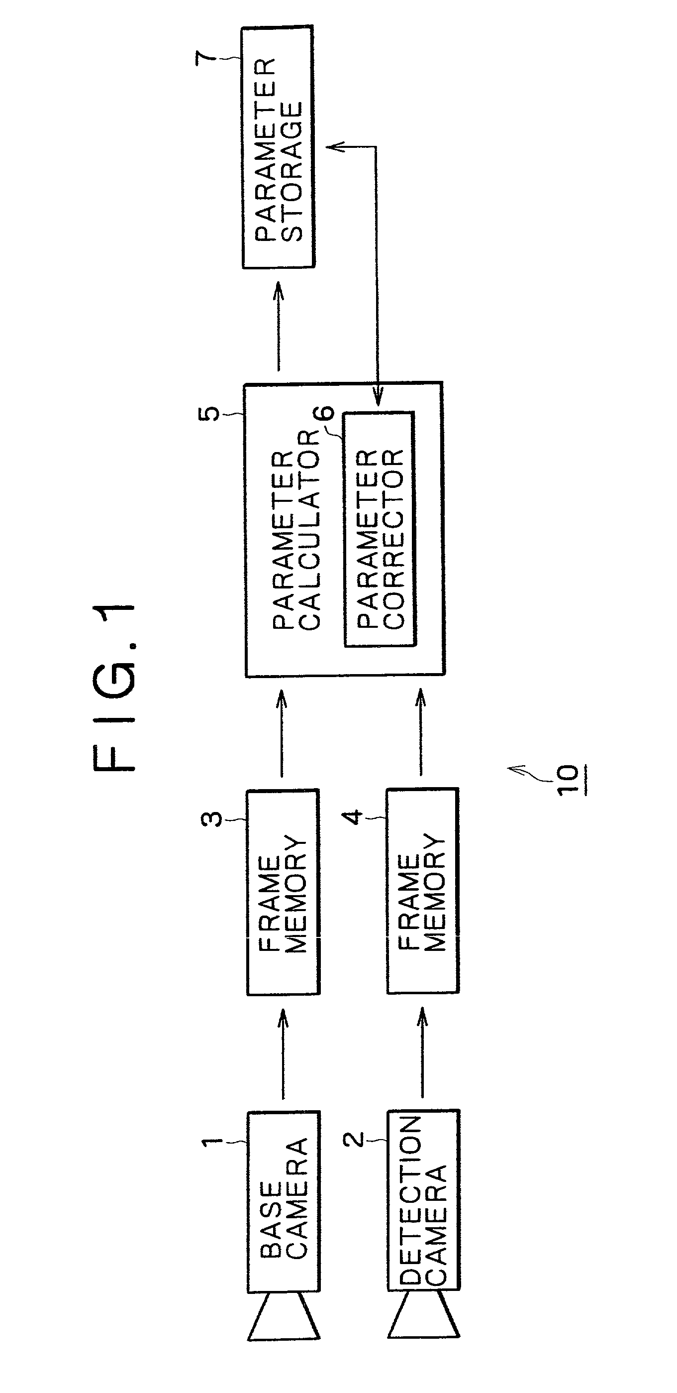
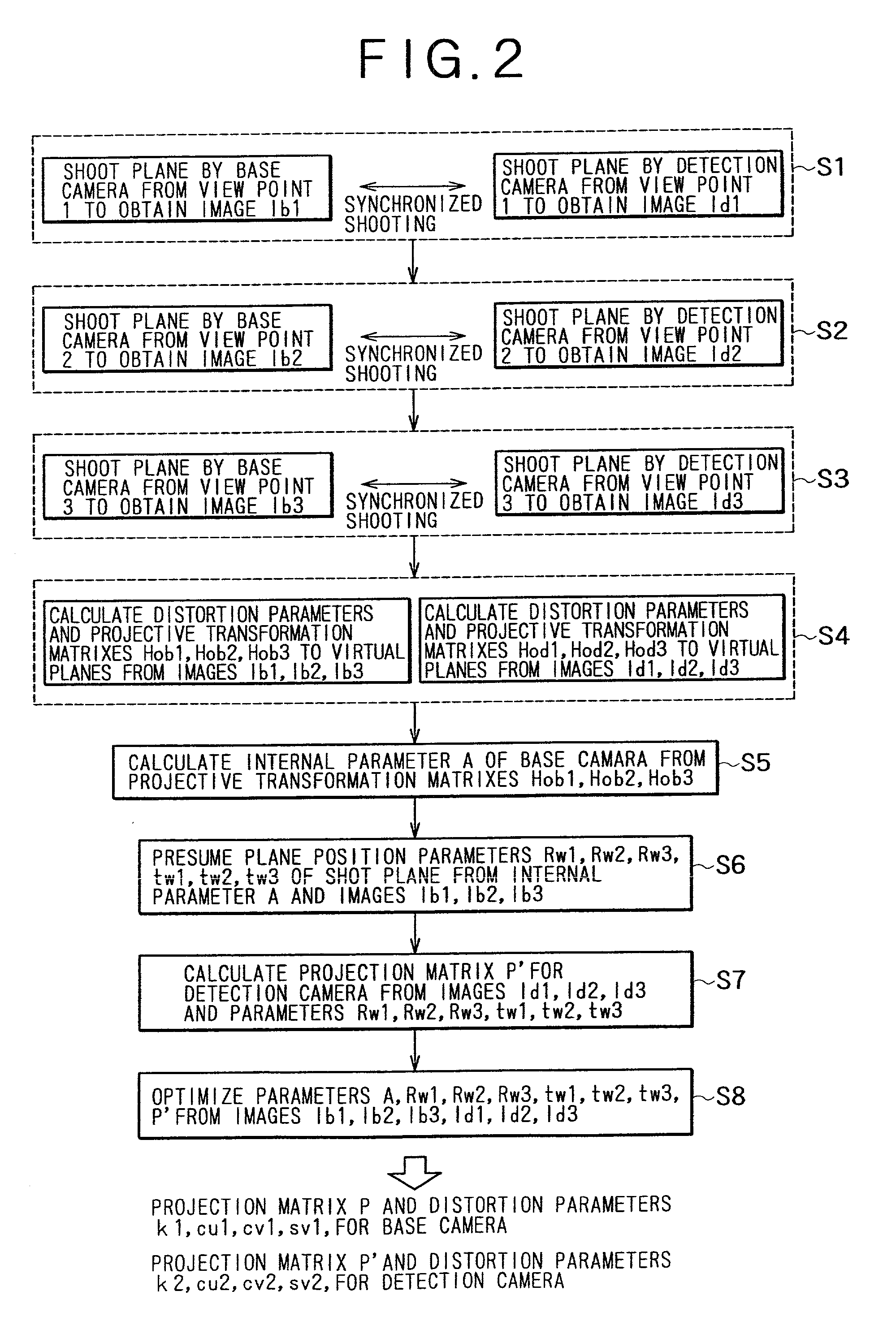
A camera calibration device capable of simply calibrating a stereo system consisting of a base camera and detection camera. First, distortion parameters of the two cameras necessary for distance measurement are presumed by the use of images obtained by shooting a patterned object plane with the base camera and the reference camera at three or more view points free from any spatial positional restriction, and projective transformation matrixes for projecting the images respectively onto predetermined virtual planes are calculated. Then internal parameters of the base camera are calculated on the basis of the projective transformation matrixes relative to the images obtained from the base camera. Subsequently the position of the shot plane is presumed on the basis of the internal parameter of the base camera and the images obtained therefrom, whereby projection matrixes for the detection camera are calculated on the basis of the plane position parameters and the images obtained from the detection camera. According to this device, simplified calibration can be achieved stably without the necessity of any exclusive appliance.

Description

BACKGROUND OF THE INVENTION[0001]1. Field of the Invention[0002]The present invention relates to a camera calibration method and device for calculating parameters representative of the characteristics of a camera and, more particularly, to such a method and device adapted for calculating parameters relative to a camera of a type which shoots an object to pick up an image thereof and outputs electronic image data. In addition, the present invention relates to a camera calibration method and device for calculating parameters necessary for distance measurement in stereographic camera calibration by the use of an arbitrary plane not restricted with regard to any spatial position.[0003]2. Description of the Prior Art[0004]Most of the existing cameras are so designed as to perform center projection with a pinhole camera model. Center projection is capable of forming a projected image by disposing the chroma value of a point M on the surface of a three-dimensional object, at an intersectio...

Claims


Application Information

Patent Timeline
Patent Type & Authority Patents(United States)
IPC IPC(8): H04N7/00G06K9/00G01B11/00G01C3/00G01C3/06G01C3/08G01C11/06G01S11/12G06T7/00H04N13/00H04N13/02H04N17/00
CPCG01C3/08G01C11/06H04N17/002G06T7/002H04N13/0246G01S11/12G06T7/85H04N13/246
Inventor IWAI, YOSHIAKIYOSHIGAHARA, TAKAYUKI
Owner SONY CORP
Learn More