Optically recorded data discrimination apparatus and associated methodology

a data discrimination and data technology, applied in the field of optically recorded data discrimination apparatus, can solve problems such as discontinuity of images and sounds, data recorded therein may not be read correctly,

Inactive Publication Date: 2006-01-10
SONY CORP
View PDF15 Cites 65 Cited by
  • Summary
  • Abstract
  • Description
  • Claims
  • Application Information

AI Technical Summary

Problems solved by technology

In the above-described optical disks, in the cases where the optical disks themselves have defects, where scratches are created on the optical disks, or where dusts are attached on the optical disks, possibilities arise that the data recorded therein may not be read correctly, due to the influences of the defects, scratches, dusts, and the like.
However, if the recorded data is video data or audio data, and the retry is repeated in an attempt to obtain correct data, the period in which the data is not read become longer, resulting in discontinuity of the images and sounds.

Method used


Image

  • Optically recorded data discrimination apparatus and associated methodology
  • Optically recorded data discrimination apparatus and associated methodology
  • Optically recorded data discrimination apparatus and associated methodology

Examples


Embodiment Construction

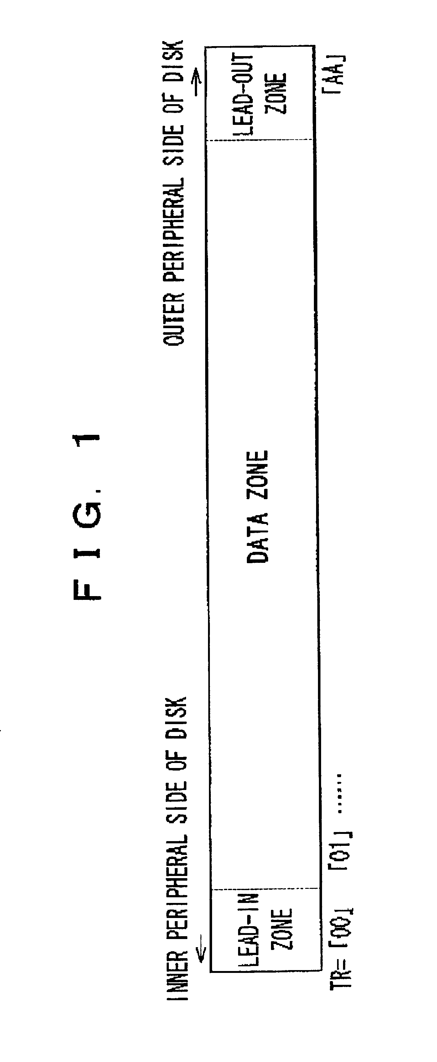
[0042]Hereinafter, the present invention will be described with reference to the drawings. FIG. 1 is a diagram showing a structure of an optical disk, for example, of a compact disk. At an inner peripheral side of the disk, a lead-in zone is formed, and at an outer peripheral side thereof, a lead-out zone is formed. The zone between the lead-in zone and the lead-out zone is a data zone.

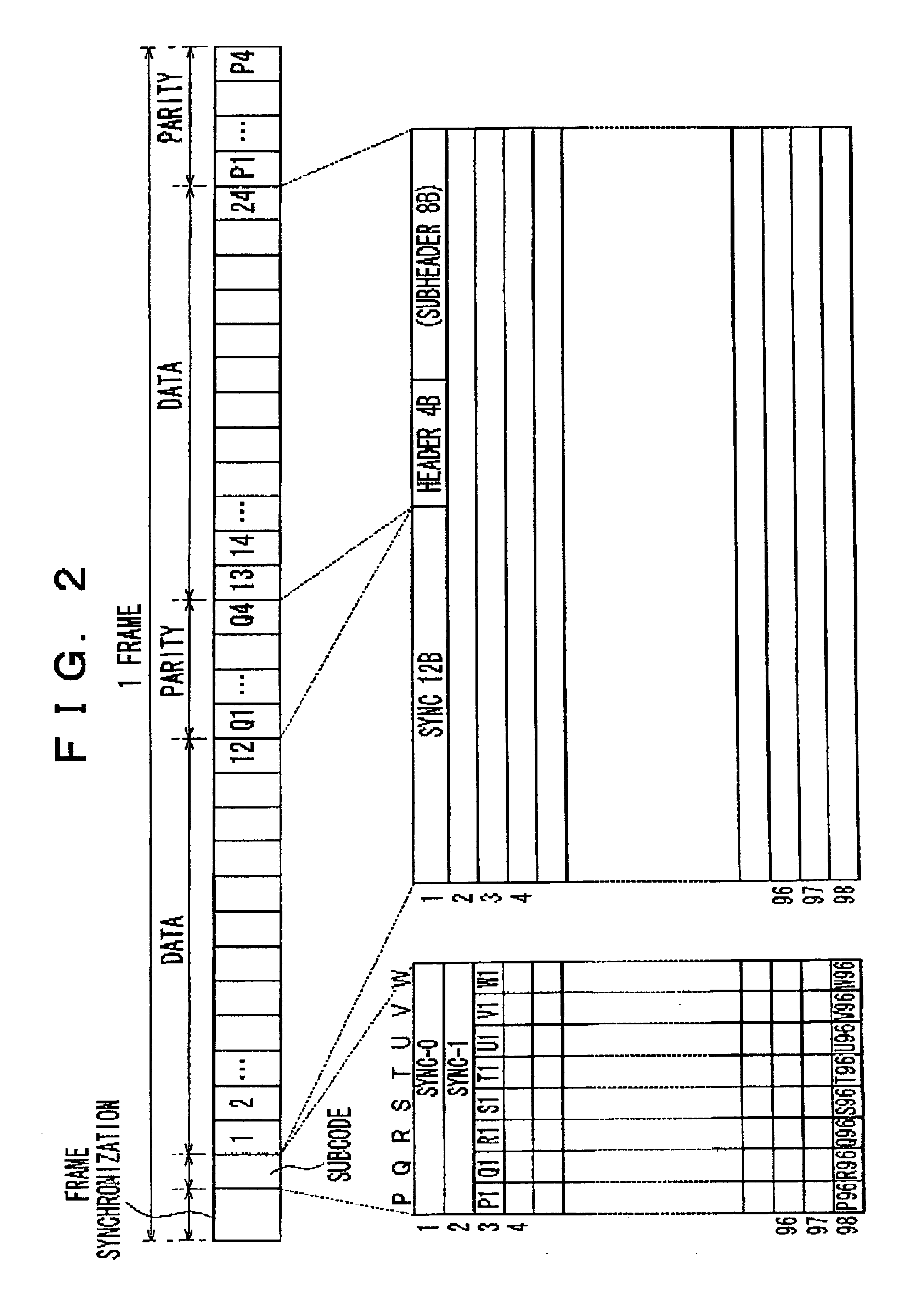
[0043]Here, one frame of a CD signal recorded in the compact disk is constituted by a frame synchronous signal and a subcode, and data and a parity, as shown in FIG. 2. The subcode is in 8 bits from P channels to W channels, and one subcode frame is constituted by the CD signal of 98 frames. In the subcode frame, first two CD signal frames are defined as a synchronous signal Sync-0 and Sync-1, and the remaining 96 frames are used to indicate information.

[0044]As shown in FIG. 3, the Q channels of the subcode (hereinafter, referred to as a “subcode Q”) include a control field (Q0 to Q4), an address fie...


PUM

PropertyMeasurementUnit
physicalaaaaaaaaaa
recording densityaaaaaaaaaa
timeaaaaaaaaaa

Abstract

The requested data is read from a DVD disk by interruption in ST46. Then, the ID information for indicating the leading end of the data, and the result of the identification by use of the EDC for indicating whether or not the data is correct are stored in ST47. When the disk is identified as a DVD-video disk and the flag is set in ST 48, and also when the number of times N of retries is identified as being larger than NR in ST50 and the read data is not identified as control data in ST51, data transmission is performed. When no flag is set, the disk identification is performed based on whether or not the data at a predetermined position on the logical format has predetermined data in ST49. When it is identified that an error has been detected in ST52 and also when the number of times N of retries becomes larger than NS in ST53, the occurrence of an error is announced.

Description

BACKGROUND OF THE INVENTION[0001]1. Field of the Invention[0002]The present invention relates to a method for identifying optical disks suitable for the case of using plural kinds of optical disks having physical specifications identical to each other, a method for reproducing optical disks, and an optical disk apparatus.[0003]2. Description of the Related Art[0004]In recent years, as technology relating to optical disks progresses, there have been suggested optical disks having physical specifications identical to each other, and having contents of recorded signals different from each other. For example, as a compact disk, on top of a CD-DA in which music data is recorded, also suggested are disks such as a CD-ROM in which computer data and the like is recorded, and a video CD (i.e. a compact disk) in which images (i.e. video images), sounds, and the like are recorded. In addition, as an optical disk called as a digital versatile disk (DVD) which has a high recording capacity attai...

Claims


Application Information

Patent Timeline
Patent Type & Authority Patents(United States)
IPC IPC(8): G11B7/005G11B19/12G11B20/12G11B20/18
CPCG11B19/12G11B19/125G11B20/1217G11B20/1879G11B20/18G11B2020/183G11B2020/10537G11B2020/1823
Inventor SHISHIDO, YUKIO
Owner SONY CORP
Why Eureka
Try Eureka