Modular conveyor belts with split belt modules

a conveyor belt and module technology, applied in the direction of conveyor parts, rollers, transportation and packaging, etc., can solve the problems of reducing the beam strength of the belt, slipping of the belt, and the seams in each row reducing the beam strength of the row, so as to increase the beam strength

Inactive Publication Date: 2006-01-17
LAITRAM LLC
View PDF30 Cites 27 Cited by
  • Summary
  • Abstract
  • Description
  • Claims
  • Application Information

AI Technical Summary

Benefits of technology

[0008]These needs and others are satisfied by a modular conveyor belt embodying features of the invention. In one version, the modular conveyor belt comprises a series of rows of belt module pieces. Each row includes first and second sets of hinge eyes along opposite first and second ends of the row. Each row also includes a group of first module pieces arranged side by side in the row and forming at least some of the first and second hinge eyes. Each row further includes a complementary group of second module pieces arranged across the row and forming other of the hinge eyes. The complementary group mates with the first group of pieces to form the belt row. The rows are then arranged end to end with the first set of hinge eyes of a row interleaved with the second set of hinge eyes of an adjacent row and pivotably connected together into a conveyor belt by hinge pins through the interleaved hinge eyes. In another version of this belt, the complementary group of second module pieces is stacked on the group of first module pieces. In yet another version, at least one of the second module pieces mates with portions of two side-by-side first module pieces. In another version, seams formed between adjacent first module pieces are offset laterally across the row from seams formed between second module pieces to avoid seams through the thickness of the row and hence increase beam strength.

Problems solved by technology

Such continuous seams would significantly decrease the beam strength of the belt.
But, even in bricklayed modular belts, the seams in each row decrease the beam strength of the row.
Besides varying the width of the belt, this separation can cause trip edges for products, pinch points for fingers, or gaps into which small conveyed products can fall or get caught.
But complex molding techniques or messy secondary manufacturing steps are required to make the attachment.
If a roller or stanchion is damaged, the module has to be removed from the belt and replaced.
Repair is not possible.

Method used


Image

  • Modular conveyor belts with split belt modules
  • Modular conveyor belts with split belt modules
  • Modular conveyor belts with split belt modules

Examples


Embodiment Construction

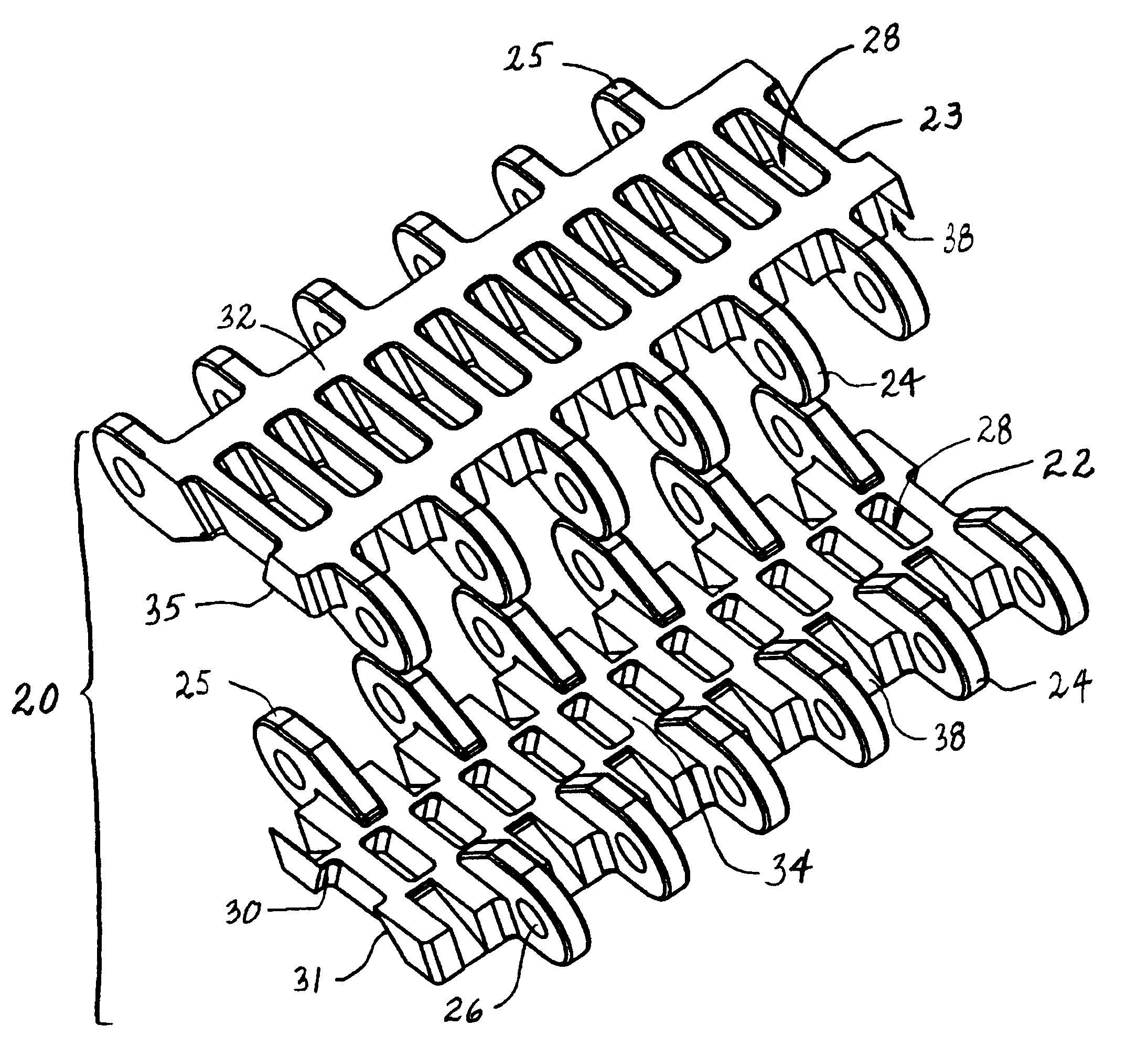
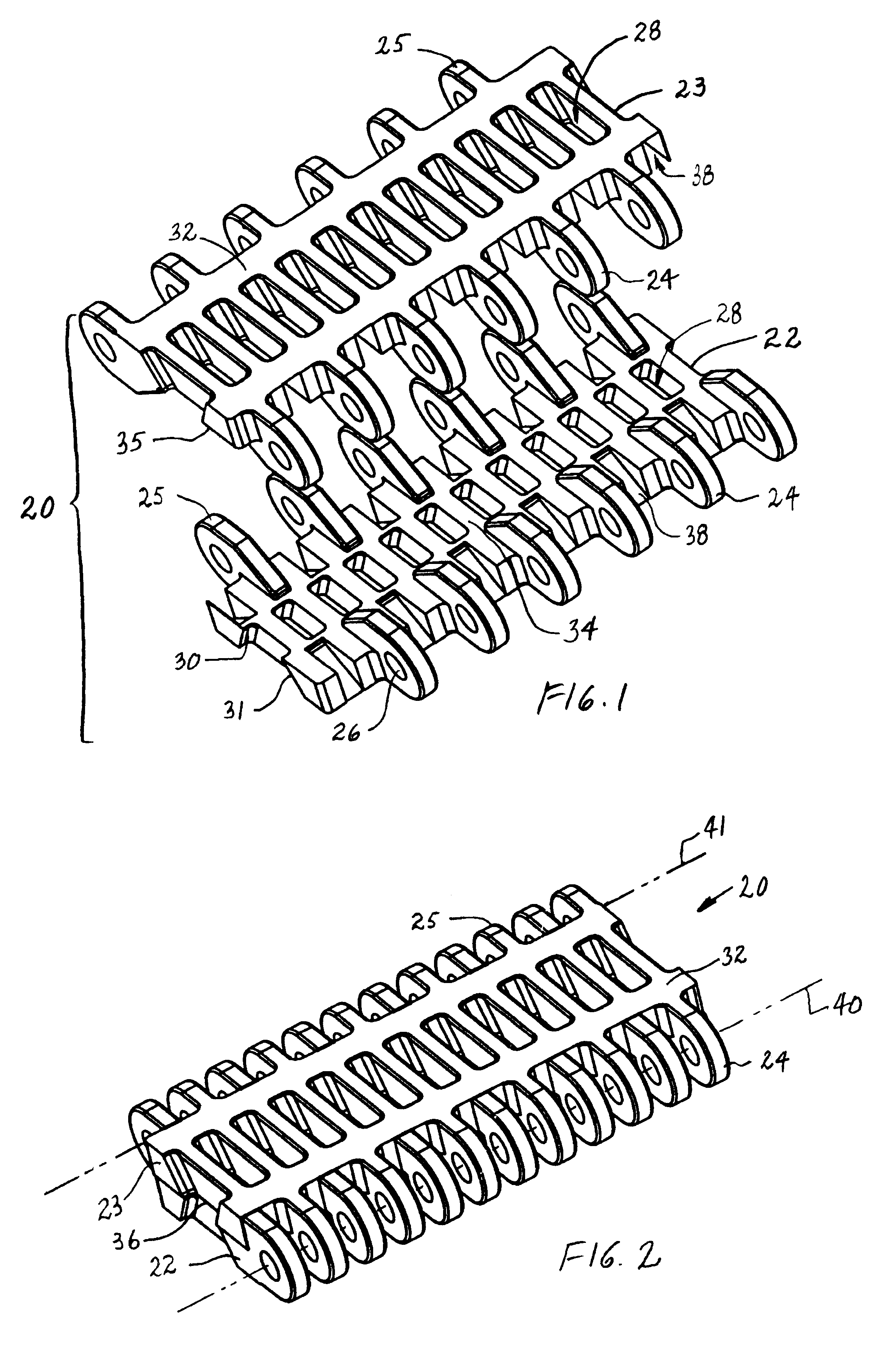
[0023]A split module for use in a modular conveyor belt having features of the invention is shown in FIGS. 1 and 2. The split module 20 is, in this example, made up of two pieces: a first piece 22 and a complementary second piece 23. Each piece includes first and second sets 24, 25 of hinge eyes along opposite first and second ends of the pieces. In this version of the split module, each piece has the same number of hinge eyes, six, along each end. As can also be seen, the first and second pieces are substantially identical in structure. The difference is that the two pieces are mirror images of each other. Each of the hinge eyes includes an aperture 26 aligned with the apertures in the other hinge eyes along that end. The aligned apertures receive a hinge pin that connects the pieces together and with other such split modules to form a conveyor belt. Each piece also has a series of trapezoidal cavities 28 spaced apart across the module body. Angled side surfaces 30, 31 of the cavit...


PUM


Abstract

Modular plastic conveyor belts constructed of split belt modules. Each module includes a first piece and a second piece. Side-by-side first pieces mate with side-by-side second pieces to form a row of belt modules. Each row has sets of hinge eyes along opposite ends. Hinge pins extending through the hinge eyes at the ends of each row connect the pieces in the row together to adjacent belt rows. Other components, such as rollers, can be inserted into and removed from the unmated pieces and retained in place by retention structure when the module pieces are mated.

Description

CROSS REFERENCE TO RELATED APPLICATIONS[0001]This application is a division of application Ser. No. 09 / 992,765, filed Nov. 6, 2001 now U.S. Pat. No. 6,681,922.BACKGROUND OF INVENTION[0002]The invention relates generally to power-driven conveyors and, more particularly, to modular conveyor belts constructed of a series of rows of belt modules split into multiple pieces and connected together by hinge pins.[0003]Conventional modular conveyor belts and chains are constructed of modular links, or belt modules, arranged end to end and often side by side in belt rows. The modules typically extend from a top article-engaging surface to a bottom drive surface through their thickness. Spaced-apart hinge eyes extending from each end of the modules include aligned openings. The hinge eyes along one end of a row of modules are interleaved with the hinge eyes along one end of an adjacent row. Pivot rods, or hinge pins, journalled in the aligned openings of interleaved hinge eyes, connect adjacen...

Claims


Application Information

Patent Timeline
Patent Type & Authority Patents(United States)
IPC IPC(8): B65G17/24B65G17/08B65G17/32
CPCB65G17/08B65G17/40B65G17/24B65G2201/02
Inventor WEISER, DAVID C.SEDLACEK, KYLE J.CORLEY, ANDREW A.
Owner LAITRAM LLC
Why Eureka
Try Eureka