Light weight, stiffened, twist resistant, extruded vehicle axle

a technology for extruding vehicle axles and axles, which is applied in the direction of manufacturing tools, transportation and packaging, and other domestic objects, can solve the problems of axle rotation or twisting, axles may rotate or twist, and the axles are periodically subjected to extreme loads, so as to reduce the weight of the axle, increase the beam strength, and resist bending and flexing

Active Publication Date: 2009-05-26
AAM INT S A R L
View PDF9 Cites 7 Cited by
  • Summary
  • Abstract
  • Description
  • Claims
  • Application Information

AI Technical Summary

Benefits of technology

[0006]The ribs are formed along the top and bottom diametrical centers of the tubular axle. These are referred to as the top and bottom dead centers when the axle tube is horizontally arranged. The ribs which extend substantially the full length of the tube increase the beam strength to resist bending and flexing. Simultaneously, the opposite end portions of the rigidifying ribs tightly fit within, and interlock with, corresponding grooves formed in the axle-receiving sockets which receive the ends of the axle.
[0007]The axle-receiving sockets could be formed in the conventional yokes which are connected, through other elements, to the wheels of a vehicle or they could be formed in a conventional carrier or housing, as for example, the housing for a vehicle differential mechanism. The formation of the ribs along the opposite, diametrically upper and lower surfaces of the axle, permits the use of relatively thinner wall cross-sections at pre-determined locations along the length of the axle. This permits a reduction in the weight of the axle, while maintaining the strength to resist extreme torsional or transverse loadings which might cause twisting or bending or flexing of the axle.
[0008]An object of this invention is to provide a lightweight axle which, although formed with thin wall sections to reduce weight, is able to resist extreme torsional or transversely directed loadings which might otherwise cause bending, flexing or twisting or rotation of the axle, and which axle can be produced relatively inexpensively.
[0009]Another object of this invention is to permit the production of extruded or cold formed tubular, high strength axles by using available equipment with a low cost die modification to produce an unusually stronger and stiffer lightweight axle.
[0010]Still a further object of this invention is to maintain a substantially homogenous grain structure of the tubular axle and ribs integrally formed along the upper and lower, diametrically opposite surface areas for providing a lighter weight, but nevertheless strong axle, at a minimal increased cost of production.
[0011]Yet another object is to provide integrally formed, longitudinally extending ribs along the top and bottom dead centers of an axle tube which help to rapidly locate and secure attachments to the axle.

Problems solved by technology

In such types of axles, the beam strength of the axles may be insufficient to resist bending or flexing of the axle under extreme loads.
Moreover, the axle may rotate or twist relative to the sockets that hold the ends of the axle when extreme torsional loads are applied.
As is known, automotive vehicle axles are periodically subjected to extreme loads, as for example, due to random, sudden contacts between the vehicle wheels and extremely rough road surface areas, which could damage the axles.
Such loads may cause the axles to twist or rotate relative to their connecting sockets or may cause some bending or flexing of the axle.
Such heavier or thicker walls result in heavier weight axles.

Method used


Image

  • Light weight, stiffened, twist resistant, extruded vehicle axle
  • Light weight, stiffened, twist resistant, extruded vehicle axle
  • Light weight, stiffened, twist resistant, extruded vehicle axle

Examples


Embodiment Construction

[0039]The following description of the preferred embodiments is exemplary in nature and is not intended to limit the invention, its application, or uses.

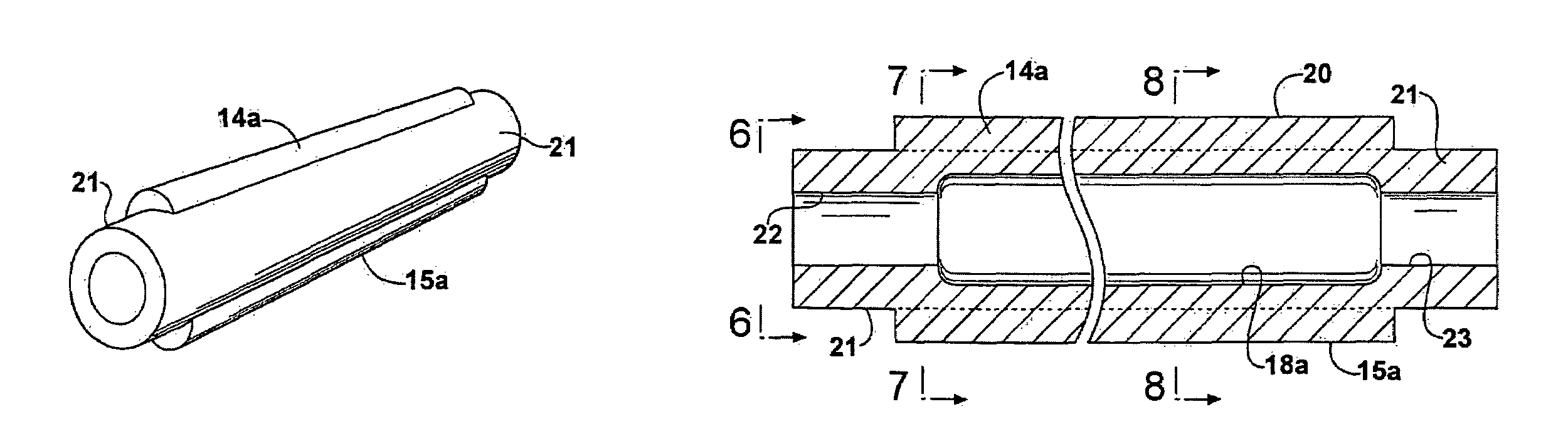
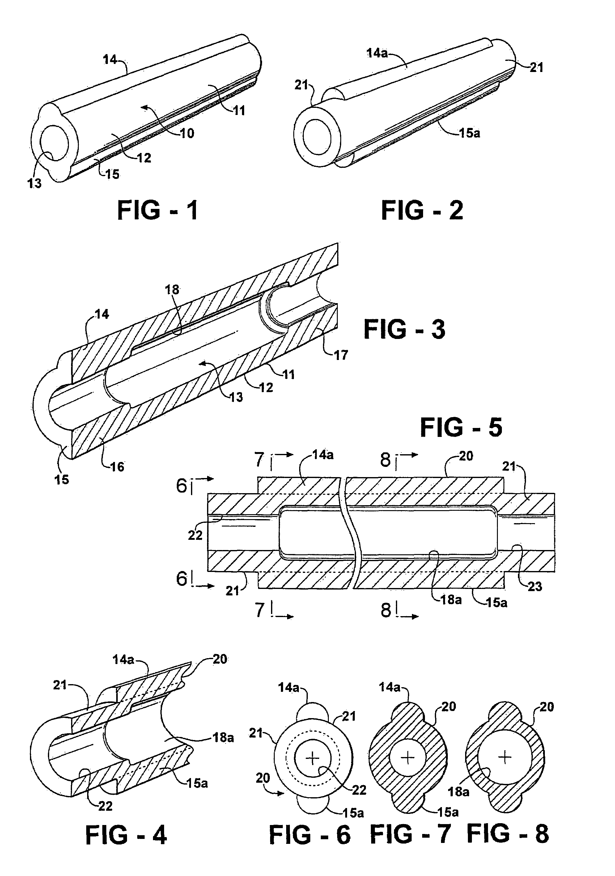
[0040]FIGS. 1 and 3 illustrate a tubular axle 10 for use with front or rear wheel assemblies used on vehicles. The axle is in the form of an elongated, hollow, shaft or tube 11 which has an exterior wall surface 12 and an interior wall surface 13. An integral radially outwardly extending bead or rib 14 is formed on the exterior wall surface. The bead is formed along the upper “dead center” of the axle when the axle is in a horizontal position. Diametrically opposite to the bead 14 is a lower bead or rib 15 integral with the lower or bottom “dead center” of the axle. Preferably, the beads are continuous and extend along substantially the full length of the axle tube.

[0041]The tube may be formed with a thickened wall end portion 16 at one end and, similarly, a thickened end wall portion 17 at its opposite end. These thickened wall sec...


PUM

PropertyMeasurementUnit
thicknessaaaaaaaaaa
lengthaaaaaaaaaa
grain structureaaaaaaaaaa

Abstract

An extruded, tubular vehicle axle for front and rear wheel applications, is formed with integral, radially outwardly extending ribs, at the radial top and bottom dead centers of the axle, and continuously extending longitudinally along substantially the entire length of the axle parallel to the axis of the axle. The opposite end portions of the axle are snugly inserted within corresponding sockets formed, for example, in a vehicle axle yoke or carrier or housing, which sockets are provided with internal grooves for snugly receiving the ribs at the respective end portions. The exterior wall surface of the axle is substantially uniform in cross-section. The interior wall surface of the axle tube may vary, at pre-selected locations, to increase or decrease the wall thicknesses at such locations. The axle resists rotation relative to the sockets, under extreme torsional loads, and resists longitudinal bending or flexing, while being of relatively light weight.

Description

BACKGROUND OF THE INVENTION[0001]This invention relates to an automotive vehicle axle for front and rear drive applications. Such axles are typically formed of extruded metal tubing. The opposite ends of the tubular axle are inserted within sockets formed, for example, on a conventional wheel support yoke or in a conventional carrier or housing through which engine power is transmitted to the axle.[0002]Various attempts to reduce the weight of components of an automotive vehicle have included forming tubular axles with portions that are thinner in wall cross-section where lesser loads are imposed upon the axle and, conversely, with thickened cross-section wall portions where the anticipated loads are greater. In such types of axles, the beam strength of the axles may be insufficient to resist bending or flexing of the axle under extreme loads. Moreover, the axle may rotate or twist relative to the sockets that hold the ends of the axle when extreme torsional loads are applied. Hence...

Claims


Application Information

Patent Timeline
Patent Type & Authority Patents(United States)
IPC IPC(8): B60B35/00
CPCB21C23/085B21C25/08B21K21/12B60B35/163B60B2310/214B60B2310/302B60B2310/318B60B2360/10B60B2900/111Y02T10/86
Inventor TYE, STEPHEN J.OYER, JAMES L.
Owner AAM INT S A R L
Why Eureka
Try Eureka