Chain link remover for cycles

a technology of chain link remover and cycle, which is applied in the direction of screwdriver, multi-purpose tools, wrenches, etc., can solve the problem that users may not easily operate the typical chain link remover, and achieve the effect of easy removal from the chain

Active Publication Date: 2006-01-24
WANG LOPIN
View PDF4 Cites 25 Cited by
  • Summary
  • Abstract
  • Description
  • Claims
  • Application Information

AI Technical Summary

Benefits of technology

[0008]The primary objective of the present invention is to provide a chain link remover for cycles including a chain support structure to support the chain and to allow the chain link to be easily removed from the chain.
[0009]In accordance with one aspect of the invention, there is provided a chain link remover comprising a base including an opening formed therein and defined by an anvil, the anvil including a vertical slot formed therein to receive a chain link pin of a chain, the base including a screw hole formed therein and aligned with the vertical slot of the anvil, a threaded shaft threaded with the screw hole of the base, and including a link ejector rod for engaging with and for removing the chain link pin from the chain, and a support device provided in the opening of the base to support the chain in the opening of the base, and to retain the chain between the anvil and the threaded shaft, and thus to allow the chain link pin to be easily disengaged or removed from the chain without holding by the users.

Problems solved by technology

However, the typical chain link removers do not include any support device to stably support and position the chain between the anvil and the threaded shaft, such that the users have to use one of their hands to hold and position the chain between the anvil and the threaded shaft, and then to use the other hand to thread or to rotate the threaded shaft relative to the chain link removers, and such that the users may not easily operate the typical chain link removers.

Method used


Image

  • Chain link remover for cycles
  • Chain link remover for cycles
  • Chain link remover for cycles

Examples


Embodiment Construction

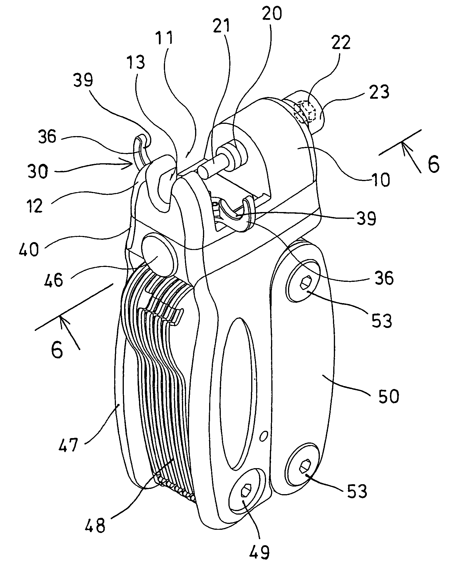
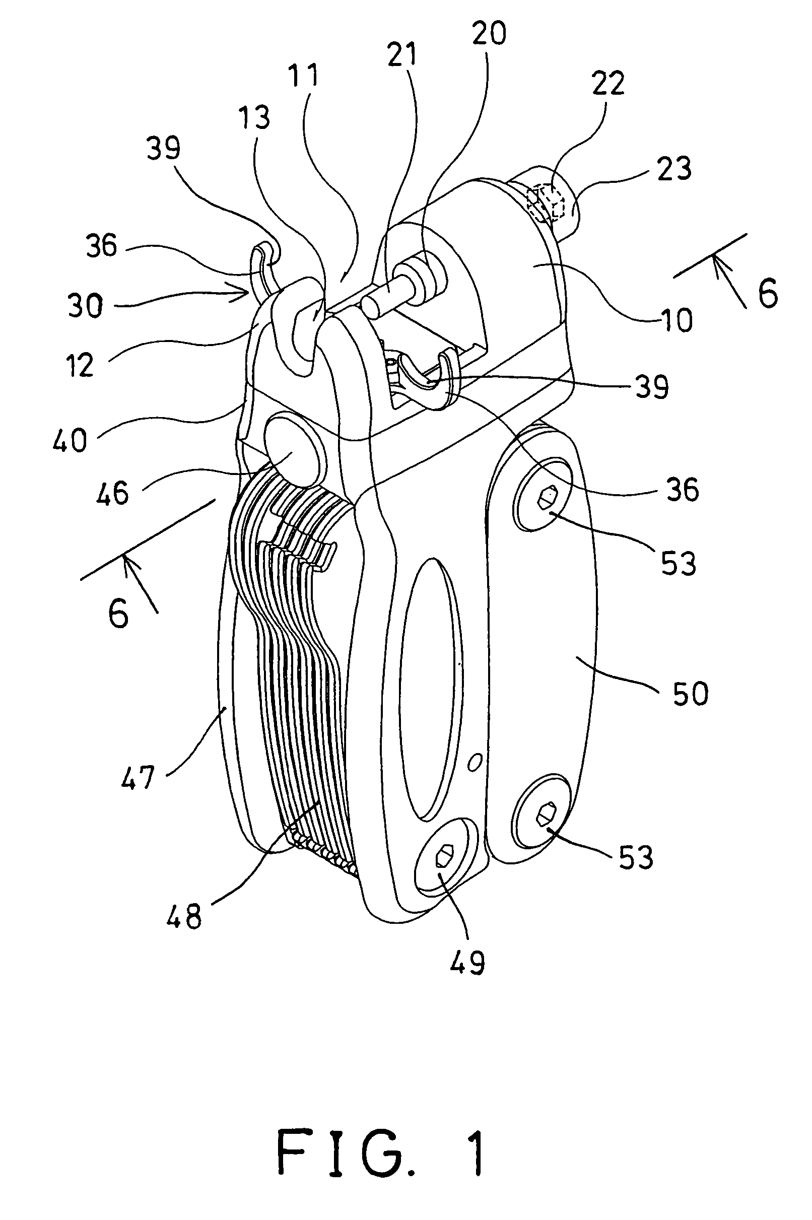
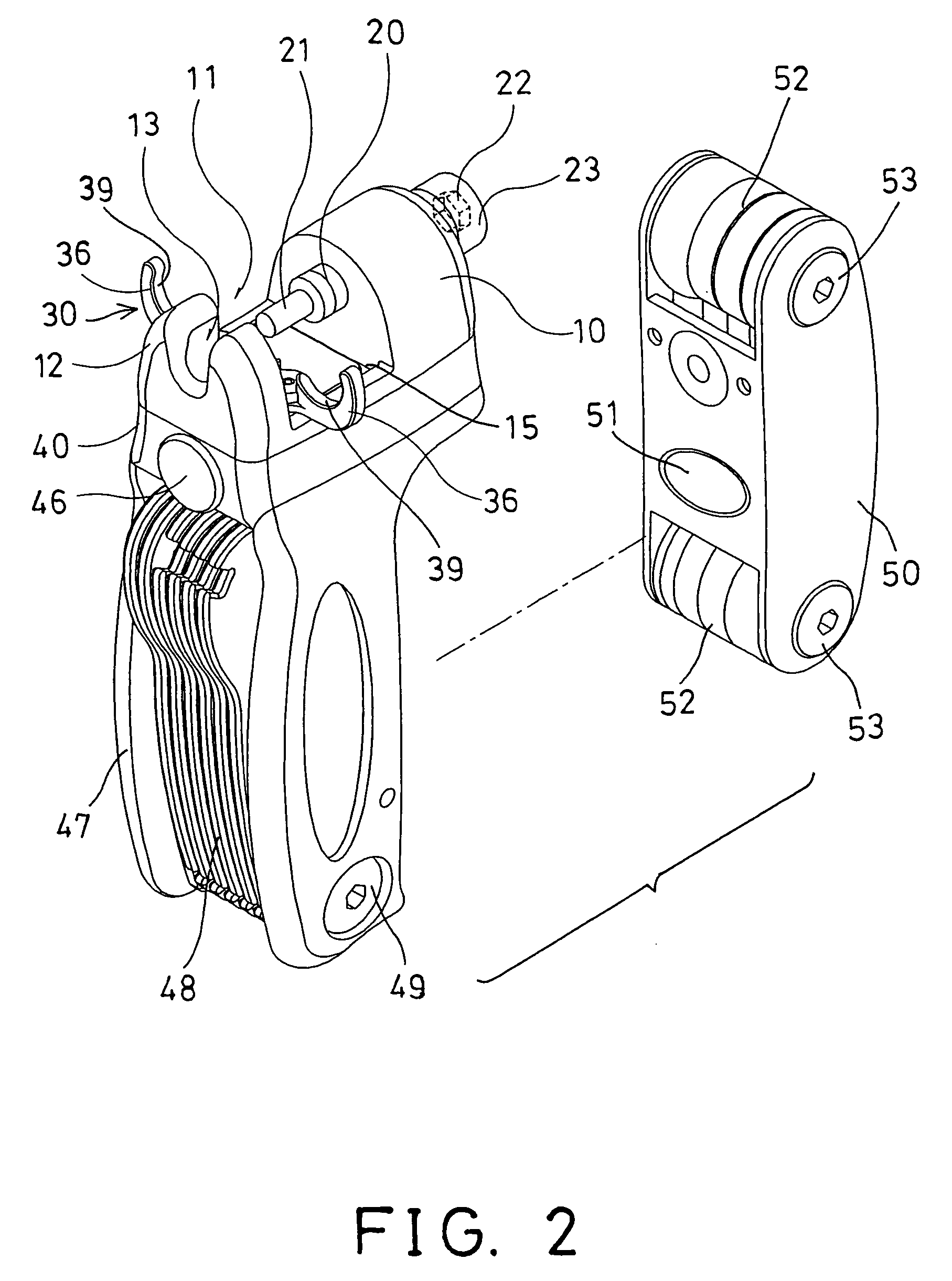
[0033]Referring to the drawings, and initially to Figure a chain link remover for cycles in accordance with the present invention comprises a base 10 including an opening 11 formed in the middle portion thereof and defined by an anvil 12 which includes a vertical slot 13 formed therein to receive chain link pins 91 removed from chain links 93 of chains 90 (FIGS. 4–5, 8 and 13).

[0034]The base 10 includes a screw hole 14 formed therein and aligned with the vertical slot 13 of the anvil 12, for threading with a threaded shaft 20 which includes a link ejector rod 21 provided on one end thereof for engaging with and for removing the chain link pins 91 from the chain links 93 of the chains 90.

[0035]The chain 90 may be engaged into the opening 11 of the base 10, and arranged to have the chain link pins 91 removed from the chain links 93 of the chains 90 with the link ejector rod 21 of the threaded shaft 20. The above described structure of the chain link remover is typical and will not be ...


PUM

PropertyMeasurementUnit
structureaaaaaaaaaa
resilienceaaaaaaaaaa
sizesaaaaaaaaaa

Abstract

A chain link remover includes a base having an opening formed by an anvil and having a screw hole for threading with a threaded shaft which has a link ejector rod to remove the chain link pin from the chain. A support device is disposed in the base to support the chain in the opening of the base, and to retain the chain between the anvil and the threaded shaft, and thus to allow the chain link pin to be easily disengaged or removed from the chain without holding by the users. The support device includes two pawls to engage with and to support the chain between the anvil and the threaded shaft, with such as resiliences.

Description

BACKGROUND OF THE INVENTION[0001]1. Field of the Invention[0002]The present invention relates to a chain link remover, and more particularly to a chain link remover for cycles having a chain support structure to support the chain and to allow the chain link to be easily removed from the chain.[0003]2. Description of the Prior Art[0004]Typical chain link removers for cycles have been developed for removing chain links from chains, and comprise an anvil to anchor or position the chain, and a threaded shaft to engage with the chain link pins, and to remove the chain link pins from the chains.[0005]For example, U.S. Pat. No. 4,967,435 to Seals, and U.S. Pat. No. 5,303,439 to Seals disclose two of the typical chain link removers for cycles, and also comprise an anvil to anchor or position the chain, and a threaded shaft to engage with the chain link pins, and to remove the chain link pins from the chains. For removing the chain link pins from the chains, the chains are required to be dis...

Claims


Application Information

Patent Timeline
Patent Type & Authority Patents(United States)
IPC IPC(8): B25B13/00B25B27/22
CPCB25B27/22
Inventor WANG, LOPIN
Owner WANG LOPIN
Why Eureka
Try Eureka