Virtual path restoration scheme using fast dynamic mesh restoration in an optical network

Inactive Publication Date: 2006-01-24
CISCO TECH INC
View PDF56 Cites 60 Cited by
  • Summary
  • Abstract
  • Description
  • Claims
  • Application Information

AI Technical Summary

Benefits of technology

[0012]In one embodiment, the present invention reduces the time and resources required to restore a failed virtual path in a mesh optical network by broadcasting or ‘constrained flooding’ of restore path request packets in the network. This ca

Problems solved by technology

However, the restoration of a circuit following a failure in

Method used


Image

  • Virtual path restoration scheme using fast dynamic mesh restoration in an optical network
  • Virtual path restoration scheme using fast dynamic mesh restoration in an optical network
  • Virtual path restoration scheme using fast dynamic mesh restoration in an optical network

Examples


Embodiment Construction

[0031]The following is intended to provide a detailed description of an example of the invention and should not be taken to be limiting of the invention itself. Rather, any number of variations may fall within the scope of the invention which is defined in the claims following the description.

Network Architecture

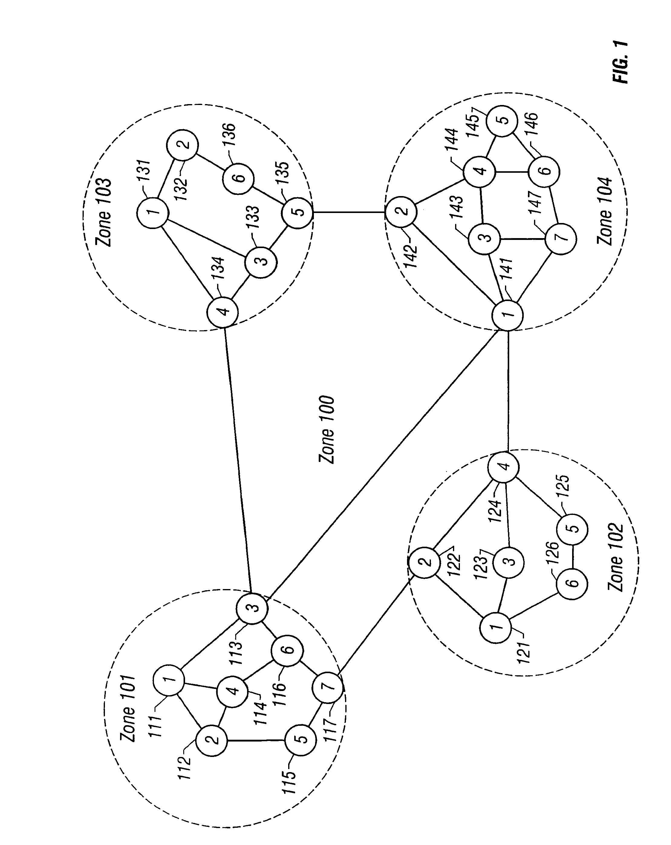
[0032]To limit the size of the topology database used by some protocols, and to limit the scope of broadcast packets (e.g., packets used for restoration), the nodes of a network can be divided into logical groups, referred to herein as “zones.” The use of zones provides several benefits. Networks employing zones can be implemented in several different ways, some of which can be implemented concurrently.

[0033]FIG. 1 illustrates an exemplary network that has been organized into a backbone, zone 100, and four configured zones, zones 101–104, which are numbered 0–4 under the protocol, respectively. The exemplary network employs a type 0 node ID, as there are relatively few zones...


PUM


Abstract

A method for restoring a virtual path, provisioned between a source and a target node, in a mesh zoned optical network is described. The method, in one embodiment, broadcasts or floods restore path requests in the network to expedite the identification of an alternate route and minimize the service disruption for failed virtual path. The flooding of requests is controlled to ensure efficient performance of the network yet guaranteeing minimum restoration time to allow critical telecommunication related traffic to flow through the network with virtually no interruption. The constant update of nodal topology by each node allows a fast identification of alternate physical path for failed virtual path.

Description

CROSS-REFERENCES TO RELATED APPLICATIONS[0001]This application is a continuation of patent application Ser. No. 09 / 750,668, entitled “A VIRTUAL PATH RESTORATION SCHEME USING FAST DYNAMIC MESH RESTORATION IN AN OPTICAL NETWORK”, filed Dec. 29, 2000, and having Ali N. Saleh, H. Michael Zadikian, Zareh Baghdasarian, and Vahid Parsi as inventors (which is a Continuation-in-Part Of patent application Ser. No. 09 / 232,397, filed Jan. 15, 1999 and entitled “A METHOD FOR ROUTING INFORMATION OVER A NETWORK”, having A. N. Saleh, H. M. Zadikian, Z. Baghdasarian, and V. Parsi as inventors). These applications are assigned to Cisco Technology, Inc., the assignee of the present invention, and are hereby incorporated by reference, in their entirety and for all purposes.[0002]This application is also related to following applications:[0003]1. Patent application Ser. No. 09 / 389,302, entitled “A NETWORK ADDRESSING SCHEME FOR REDUCING PROTOCOL OVERHEAD IN AN OPTICAL NETWORK”, filed Sep. 2, 1999 and hav...

Claims


Application Information

Patent Timeline
IPC IPC(8): H04L12/28G01R31/08G06F15/16
CPCH04L45/02H04L45/32H04L45/28
Inventor SALEH, ALI N.ZADIKIAN, H. MICHAELBAGHDASARIAN, ZAREHPARSI, VAHID
Owner CISCO TECH INC
Why Eureka
Try Eureka