Optical wavelength cross connect architectures using wavelength routing elements

a technology of optical wavelength and routing elements, applied in the field of fiberoptic communications, can solve the problems of limited efficiency of an arrangement such as the one shown in fig. 1 and the explosion of global bandwidth demand, and achieve the effect of expanding the cross-connect function

Inactive Publication Date: 2006-01-24
ALTERA CORP
View PDF15 Cites 10 Cited by
  • Summary
  • Abstract
  • Description
  • Claims
  • Application Information

AI Technical Summary

Benefits of technology

[0017]In still further embodiments, arrays of smaller cross connects configured using wavelength routing elements may be arranged to provide larger cross-connect functions. For example, a K×K optical wavelength cross connect may be configured to distribute spectral bands comprised by K input optical signals among K output optical signals as an array of interconnected optical wavelength cross connects, at least one of which is smaller than K×K. The mapping of the spectral bands from the input ports to the output ports is determined by states of the interconnected optical wavelength cross connects. Examples of array configurations that may be used include crossbar arrays, Benes arrays, Benes

Problems solved by technology

The Internet and data communications are causing an explosion in the global demand for bandwidth.
This makes it difficult and expensive to scale DWDM networks using SONET/SDH technology.
The efficiency of

Method used


Image

  • Optical wavelength cross connect architectures using wavelength routing elements
  • Optical wavelength cross connect architectures using wavelength routing elements
  • Optical wavelength cross connect architectures using wavelength routing elements

Examples


Embodiment Construction

1. Introduction

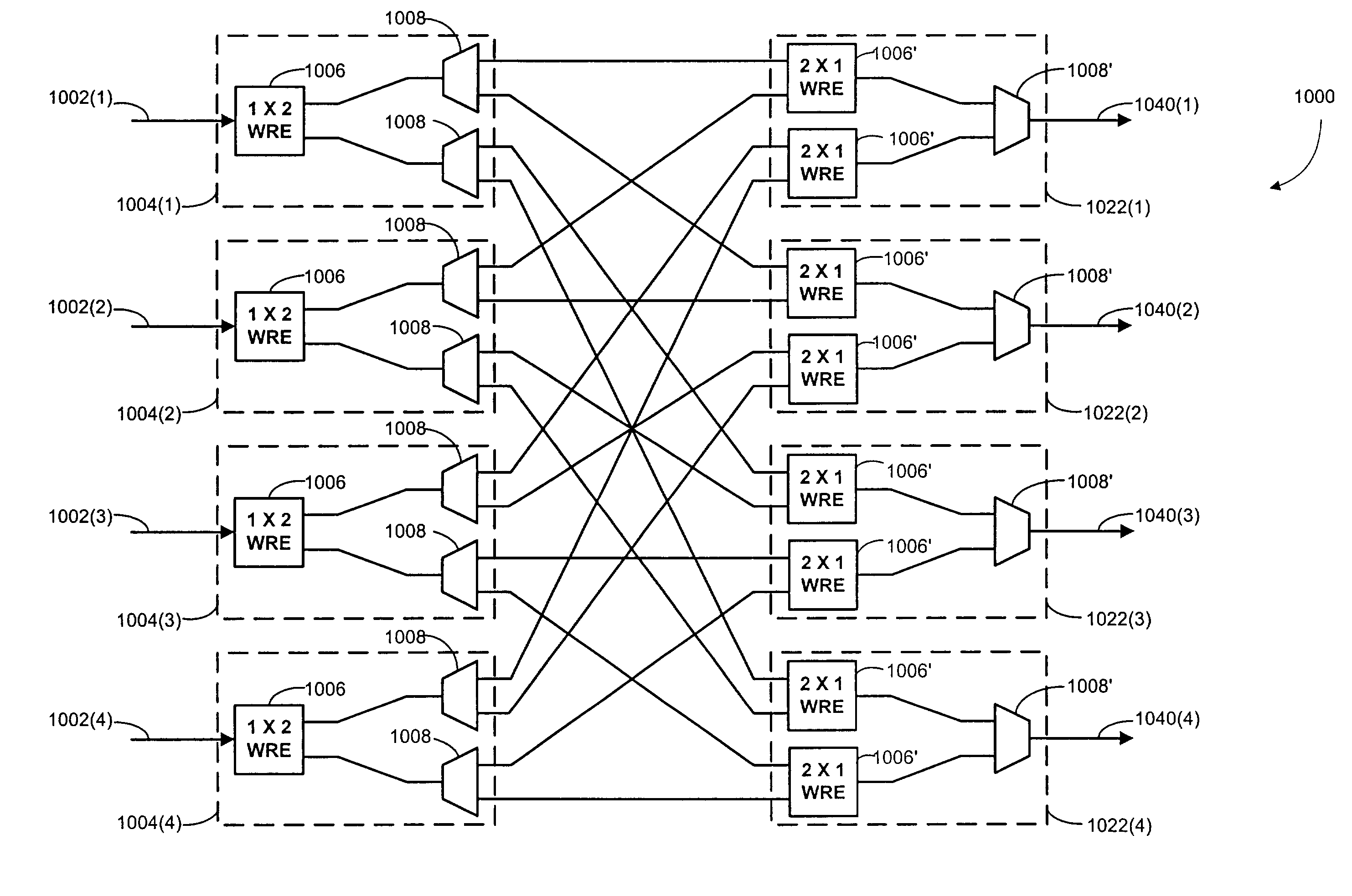
[0033]The following description sets forth embodiments of optical wavelength cross-connect architectures according to the invention. The general operation of such cross-connect architectures is to receive P input signals at respective input ports and output Q output signals at respective output ports. Each of the input and output signals comprises a plurality of spectral bands, with the cross connect capable of achieving a configuration that results in a desired redistribution of input spectral bands corresponding to equivalent channels among the output signals. Although the signals could each have a continuous spectrum, adjacent segments of which could be considered different spectral bands, it is generally contemplated that the spectrum of the incoming light will have a plurality of spaced bands, denoted as corresponding to channels 1, 2, 3, . . . N. In some instances, the examples provided herein focus on symmetric cross connects in which P=Q, but this is not a req...


PUM


Abstract

An optical wavelength cross connect is provided to receive multiple input optical signals that each have multiple spectral bands and to transmit multiple output optical signals that each have one or more of those spectral bands. The optical wavelength cross connect includes multiple wavelength routing elements, which are optical components that selectively route wavelength components between one optical signal and multiple optical signals in either direction according to a configurable state.

Description

CROSS REFERENCES TO RELATED APPLICATIONS[0001]This application is a continuation-in-part application of U.S. patent application Ser. No. 10 / 093,844, entitled “OPTICAL WAVELENGTH CROSS CONNECT ARCHITECTURES USING WAVELENGTH ROUTING ELEMENTS,” filed Mar. 8, 2002 by Edward J. Bortolini el al., the entire disclosure of which is herein incorporated by reference for all purposes. This application is also related to the following commonly assigned applications, the entire disclosure of each of which is also herein incorporated by reference for all purposes: U.S. patent application Ser. No. 10 / 093,843 entitled “METHODS FOR PERFORMING IN-SERVICE UPGRADES OF OPTICAL WAVELENGTH CROSS CONNECTS,” filed Mar. 8, 2002 by Edward J. Bortolini; U.S. patent application Ser. No. 10 / 126,189, entitled “MULTI-CITY DWDM WAVELENGTH LINK ARCHITECTURES AND METHODS FOR UPGRADING,” filed Apr. 19, 2002 by S. Christopher Alaimo et al.; and U.S. patent application Ser. No. 10 / 150,810, entitled “BIDIRECTIONAL WAVELE...

Claims


Application Information

Patent Timeline
IPC IPC(8): G02B6/28H04J14/02H04Q11/00
CPCH04J14/0204H04J14/0212H04J14/0213H04J14/0217H04J14/0297H04Q11/0005H04J14/0209H04Q2011/0075H04J14/0219H04J14/0282H04Q2011/0016H04Q2011/0024H04Q2011/0026H04Q2011/0032H04Q2011/0043H04Q2011/0052
Inventor WEVERKA, ROBERT T.
Owner ALTERA CORP
Why Eureka
Try Eureka