System and method for reducing dynamic range and improving linearity in an amplication system

a linear amplifier and dynamic range technology, applied in the field of electronic devices, can solve the problems of inefficient linear amplifier operation in these types of signals, general non-operational high efficiency, and additional challenges, and achieve the effect of reducing peaks, reducing peak signals, and reducing peaks associated

Inactive Publication Date: 2005-06-16
NORTHROP GRUMMAN SYST CORP
View PDF14 Cites 96 Cited by
  • Summary
  • Abstract
  • Description
  • Claims
  • Application Information

AI Technical Summary

Problems solved by technology

However, they are generally not operated at high efficiency due to the need to provide high linearity.
Time varying envelopes present an additional challenge.
Thus, there is customarily an inherent tradeoff between linearity and efficiency in amplifier designs.
Therefore, the operation of the linear amplifiers in these types of signals is very inefficient, since the amplifiers must have their supply voltage sized to handle the large peak voltages even though the signals are much smaller a substantial portion of the time.
Additionally, the size and cost of the power amplifier is generally proportional to the required peak output power of the amplifier.
The cost of the amplifier scales with its, peak power.
Several other circuit costs including heat sinks and DC-DC power supplies scale inversely to peak power and dissipated heat (which results from the electrical inefficiency).
Related base station costs of AC-DC power supplies, back-up batteries, cooling, and circuit breakers also scale inversely with efficiency as does the electrical operating costs.
Clearly, improving DC-RF efficiency is a major cost saver both for manufacture and operation.
These signals, while rich in information content, are costly to transmit in terms of hardware and electrical consumption.
There are a variety of schemes to clip a signal which result in substantial amounts of signal distortion and / or OOB emissions.
The strict regulation of OOB emissions is often the limiting factor in the degree to which peak signals can be limited by clipping.

Method used


Image

  • System and method for reducing dynamic range and improving linearity in an amplication system
  • System and method for reducing dynamic range and improving linearity in an amplication system
  • System and method for reducing dynamic range and improving linearity in an amplication system

Examples


Embodiment Construction

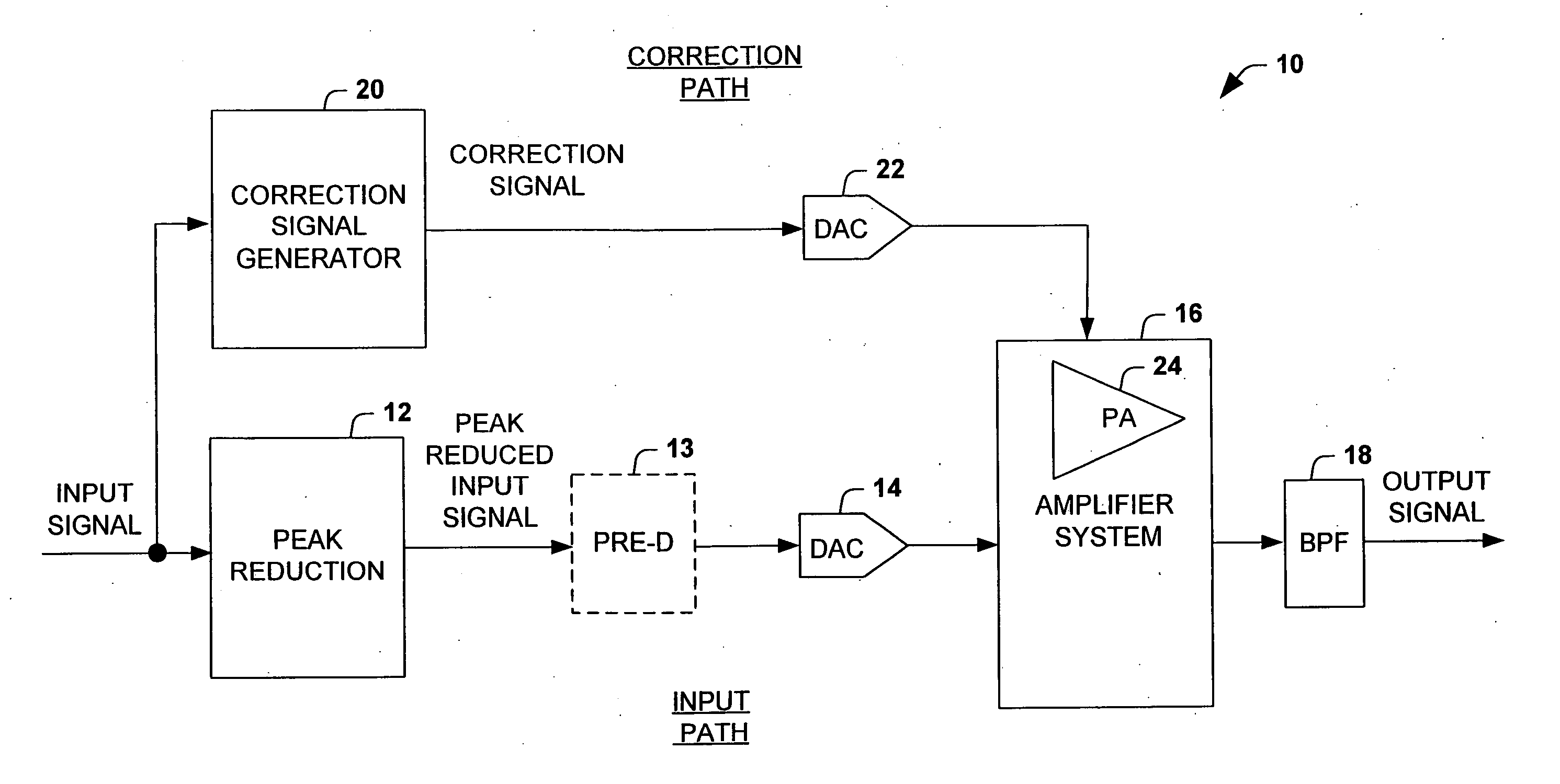
[0023] The present invention relates to an amplification system and method that reduces distortion and / or OOB emissions in amplifier systems such as those resulting from the clipping of peaks associated with an input signal. The system and method provide one or more corrections to the reduced peak signal associated with signal distortion and OOB emissions that result from the peak reduction. Therefore, smaller (less power capacity) and less costly power amplifiers can be employed to achieve similar performance. A second result is improved amplifier system efficiency as compared to amplifier systems with much larger less efficient power amplifiers. The present invention can be employed in wireless standards such as WCDMA, OFDM, multi-carrier versions of GSM and CDMA 2000 and other wireless standards and applications.

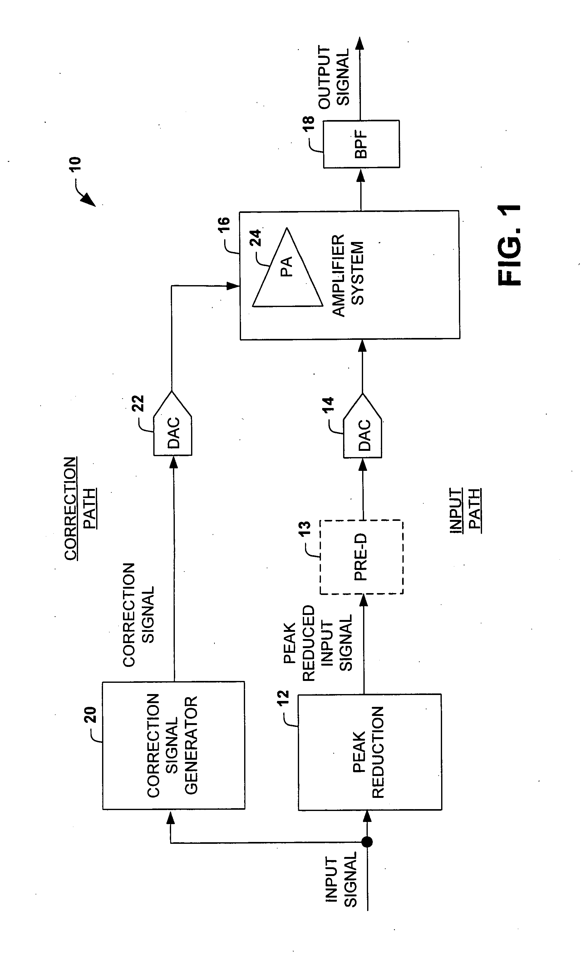
[0024]FIG. 1 illustrates an amplification system 10 in accordance with an aspect of the present invention. The amplification system 10 includes a peak reduction componen...


PUM


Abstract

An amplification system and method is provided that reduces peaks associated with an input signal, and provides correction, in one or more spectral bands, to signal distortion and out-of-band emissions that result from the peak reduction. The correction signal that removes signal distortion and OOB emissions associated with the peak reduction can be calculated or electronically derived. The correction signal can be combined with the peak reduced signal prior to or after amplification of the peak reduced input signal.

Description

CROSS REFERENCE TO RELATED APPLICATIONS [0001] The present application is related to New Robinson U.S. patent application entitled “Digital Cross Cancellation System”, filed Jul. 23, 2003, Attorney Docket No. NG(ST)-6400, and assigned to the same assignee as the present application.TECHNICAL FIELD [0002] The present invention relates generally to electronic devices, and more particularly to a system and method for reducing dynamic range and improving linearity in an amplification system. BACKGROUND OF THE INVENTION [0003] RF power amplifiers used for wireless communication transmitters, with spectrally efficient modulation formats, require high linearity to preserve modulation accuracy and to limit spectral regrowth. Typically, a linear amplifier, Class-A type, Class-AB type or Class-B is employed to faithfully reproduce input signals and to limit the amplifier output within a strict emissions mask. Linear amplifiers are capable of electrical (DC power in to RF power out or DC-RF) e...

Claims


Application Information

Patent Timeline
Patent Type & Authority Applications(United States)
IPC IPC(8): H03F3/20H03F1/02H03F1/32H04B1/04
CPCH03F1/3223H03F2200/331H03F1/3241
Inventor ROBINSON, IAN
Owner NORTHROP GRUMMAN SYST CORP
Why Eureka
Try Eureka