Array Camera Architecture Implementing Quantum Dot Color Filters

a color filter and array camera technology, applied in the field of array cameras, can solve the problems of large performance constraints, limitations in the dynamic range, and the camera is subject to various performance constraints

Inactive Publication Date: 2015-10-29
FOTONATION LTD
View PDF6 Cites 98 Cited by
  • Summary
  • Abstract
  • Description
  • Claims
  • Application Information

AI Technical Summary

Benefits of technology

[0015]An array camera module in accordance with another embodiment again includes an imager array including: a plurality of focal planes, where each focal plane comprises a plurality of rows of pixels that also form a plurality of columns of pixels and each focal plane is contained within a region of the imager array that does not contain pixels from another focal plane; control circuitry configured to control the capture of image information by the pixels within the focal planes; and sampling circuitry configured to convert pixel outputs into digital pixel data. In addition, the array camera module also includes an optic array of lens stacks aligned with respect to the imager array so that an image is formed on each focal plane by a separate lens stack in said optic array of lens stacks, where the optic array including: lens elements formed on substrates separated by spacers, where the lens elements, substrates and spacers are configured to form a plurality of optical channels; at least one aperture located within each optical channel; at least one spectral filter located within each optical channel, where each spectral filter is configured to pass a specific spectral band of ultraviolet light; and at least one quantum dot color filter located within each optical channel to receive the specific spectral band of ultraviolet light passed by the at least one spectral filter located within the optical channel, where the at least one quantum dot color filter is configured to emit a spectral band of visible light in response to incident ultraviolet light passed by the at least one spectral filter.

Problems solved by technology

Cameras are subject to various performance constraints.
The performance constraints for cameras include, among others, dynamic range, signal to noise (SNR) ratio and low light sensitivity.
These performance constraints are greatly magnified in cameras designed for mobile systems due to the nature of design constraints.
Due to limits in light gathering ability, reduced SNR, limits in the dynamic range, and reduced sensitivity to low light scenes, the cameras in mobile cameras show poor performance.

Method used


Image

  • Array Camera Architecture Implementing Quantum Dot Color Filters
  • Array Camera Architecture Implementing Quantum Dot Color Filters
  • Array Camera Architecture Implementing Quantum Dot Color Filters

Examples


Embodiment Construction

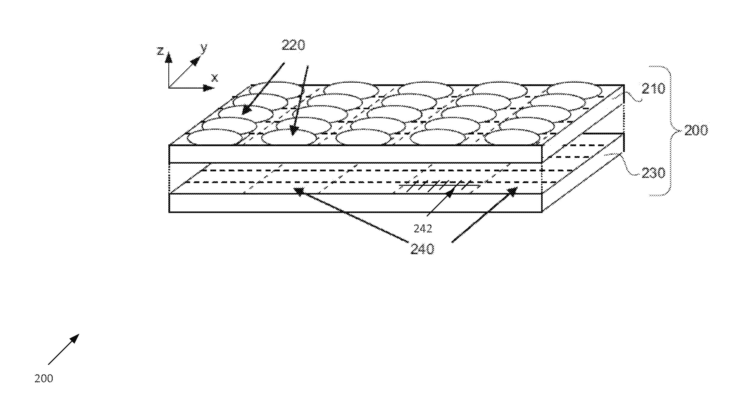
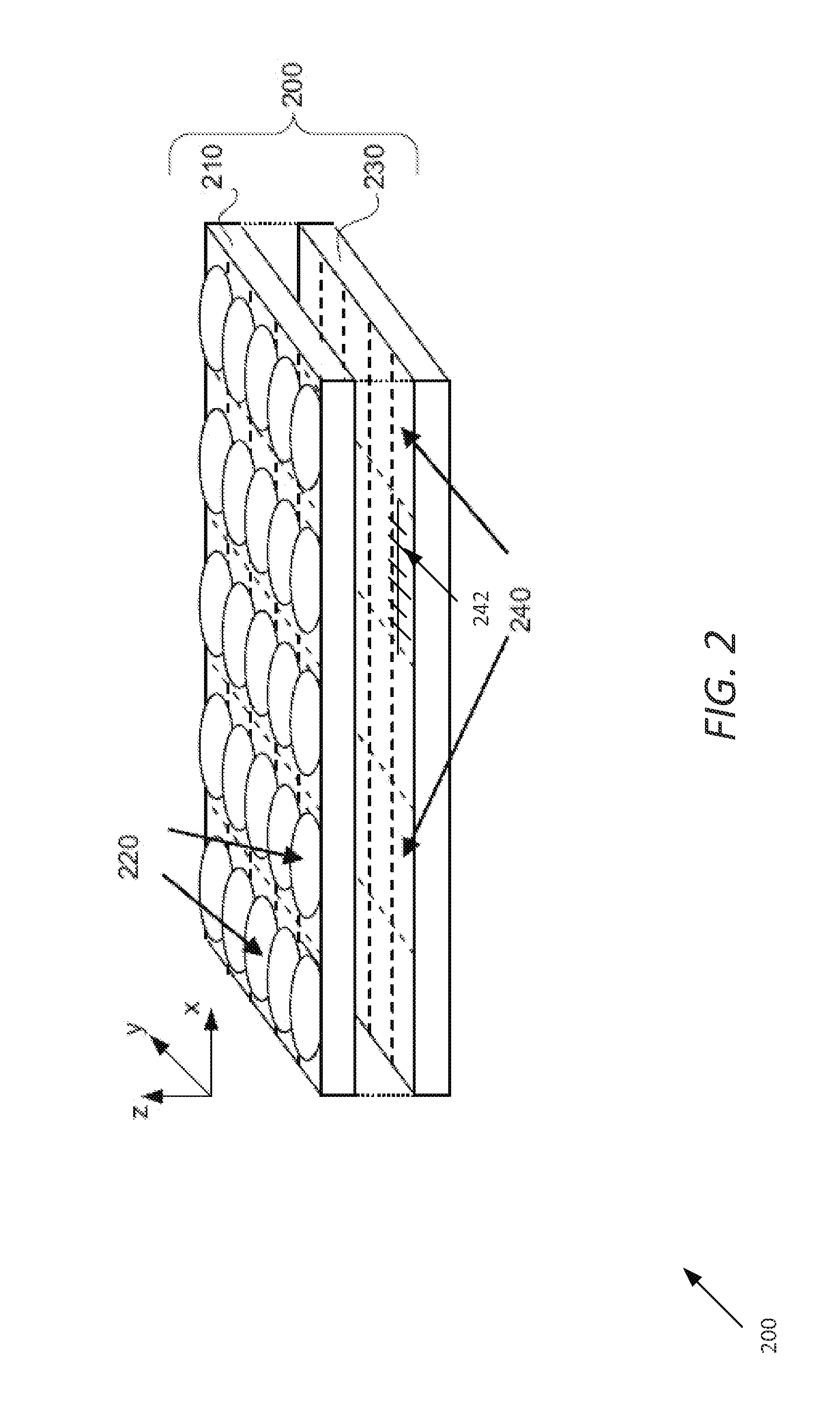
[0030]Turning now to the drawings, systems and methods for implementing quantum dot color filters on array cameras in accordance with embodiments of the invention are illustrated. Many embodiments relate to using quantum dot films color filters in camera modules of array cameras.

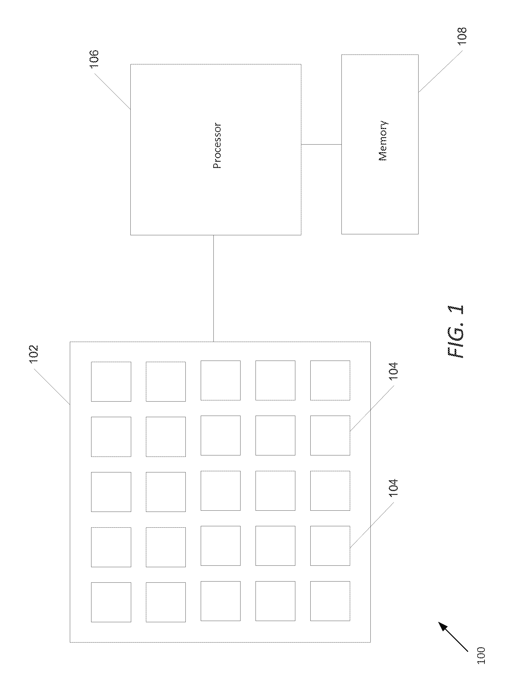
[0031]Array cameras including camera modules that can be utilized to capture image data from different viewpoints (i.e. light field images) are disclosed in U.S. patent application Ser. No. 12 / 935,504 entitled “Capturing and Processing of Images using Monolithic Camera Array with Heterogeneous Imagers” to Venkataraman et al. In many instances, fusion and super-resolution processes such as those described in U.S. patent application Ser. No. 12 / 967,807 entitled “Systems and Methods for Synthesizing High Resolution Images Using Super-Resolution Processes” to Lelescu et al., can be utilized to synthesize a higher resolution 2D image or a stereo pair of higher resolution 2D images from the lower resolution images...


PUM


Abstract

Systems and methods in accordance with embodiments of the invention utilize array cameras incorporating quantum dot color filters. One embodiment includes: lens elements formed on substrates separated by spacers, where the lens elements, substrates and spacers form a plurality of optical channels; at least one aperture located within each optical channel; at least one spectral filter located within each optical channel, where each spectral filter is configured to pass a specific spectral band of light; and at least one quantum dot color filter located within each optical channel to receive the specific spectral band of light passed by the at least one spectral filter located within the optical channel, where the at least one quantum dot color filter is configured to emit a spectral band of light having a bandwidth that is narrower than the specific spectral band of light passed by the at least one spectral filter.

Description

FIELD OF THE INVENTION[0001]The present invention generally relates to array cameras and more specifically to systems and methods for implementing quantum dot color filters in array cameras.BACKGROUND[0002]In capturing an image in a typical camera, light enters through an opening (aperture) at one end of the camera and is directed to a focal plane by an optical array. In most cameras a lens stack including one or more layers of optical elements are placed between the aperture and the focal plane to focus light onto the focal plane. The focal plane consists of light sensitive pixels that generate signals upon receiving light via the optic array. Commonly used light sensitive sensors for use as light sensitive pixels include CCD (charge-coupled device) and CMOS (complementary metal-oxide-semiconductor) sensors.[0003]Filters are often employed in the camera to selectively transmit lights of certain wavelengths onto the light sensitive pixels. In conventional cameras a Bayer filter mosa...

Claims


Application Information

Patent Timeline
Patent Type & Authority Applications(United States)
IPC IPC(8): H04N5/225H04N9/04H01L27/146G02B3/00G02B5/20
CPCH04N5/2257G02B3/0037G02B5/201G02B5/208H04N5/2254B82Y20/00H04N9/045H01L27/14621Y10S977/774Y10S977/834H01L27/14625G02B13/003H01L27/14618H01L2924/0002H04N23/957H04N25/6153H04N25/134H01L2924/00H04N23/57
Inventor VENKATARAMAN, KARTIKDUPARRE, JACQUESMULLIS, ROBERT
Owner FOTONATION LTD
Why Eureka
Try Eureka