Resolution on demand

a technology of image resolution and demand, applied in the field of image resolution on demand, can solve the problems of high-resolution imagery, high cost of resolution or dangerous collection, and images collected in the pan waveband

Active Publication Date: 2013-11-05
RAYTHEON CO
View PDF12 Cites 97 Cited by
  • Summary
  • Abstract
  • Description
  • Claims
  • Application Information

AI Technical Summary

Benefits of technology

[0012]Exemplary embodiments according to the present invention provide an imaging system and method for providing resolution on demand. The imaging system and method for providing resolution on demand herein provide high-resolution imagery that measures upwelling radiance and adapts sensor settings to collect high-resolution imagery if there is ample upwelling radiance and / or illuminates regions of interest to provide sufficient illumination if there is insufficient upwelling radiance. The imaging system and method therefore adapt to the amount of upwelling radiance and provide additional illumination to regions of interest where that ambient level is insufficient to collect higher resolution imagery than would be possible without the illumination. The imaging system and method further provide fused imagery including image frames collected without illumination and image frames that are collected using illumination.
[0020]The method may further correct geometric aberrations caused by telescope errors or pointing motion when Q is greater than 2.
[0025]The cueing controller may further determine an optimal path to illuminate the at least one region of interest based on a prioritized scheduling algorithm, and command the at least one illuminator to illuminate the at least one region of interest in accordance with the optimal path.

Problems solved by technology

A fundamental issue regarding such imaging systems is obtaining high-resolution imagery.
Resolution may be expensive to obtain or dangerous to collect, requiring large telescopes and / or close proximity to a potential threat.
However, images collected in the PAN waveband use intensifiers and / or designs with large pixels and are generally low in resolution.
Those skilled in the art recognize there is an inherent limitation to resolution for a given size telescope due to diffraction effects, though many imaging systems purposely degrade their resolution to enable wider area coverage or greater signal collection.
A high-resolution image, for example, is one where diffraction effects are the collecting dominant limitation to resolution.
In addition, the USWIR waveband has generally not been considered suitable for high-resolution imaging at night as only very warm objects may be viewed at night unless a system has very degraded spatial resolution relative to the diffraction limit or collects energy for extensive (non-practical) periods of time.
However, these systems do not combine illuminated and non-illuminated image frames, or adapt to ambient atmospheric or spectral conditions by using illuminators.

Method used


Image

  • Resolution on demand
  • Resolution on demand
  • Resolution on demand

Examples


first embodiment

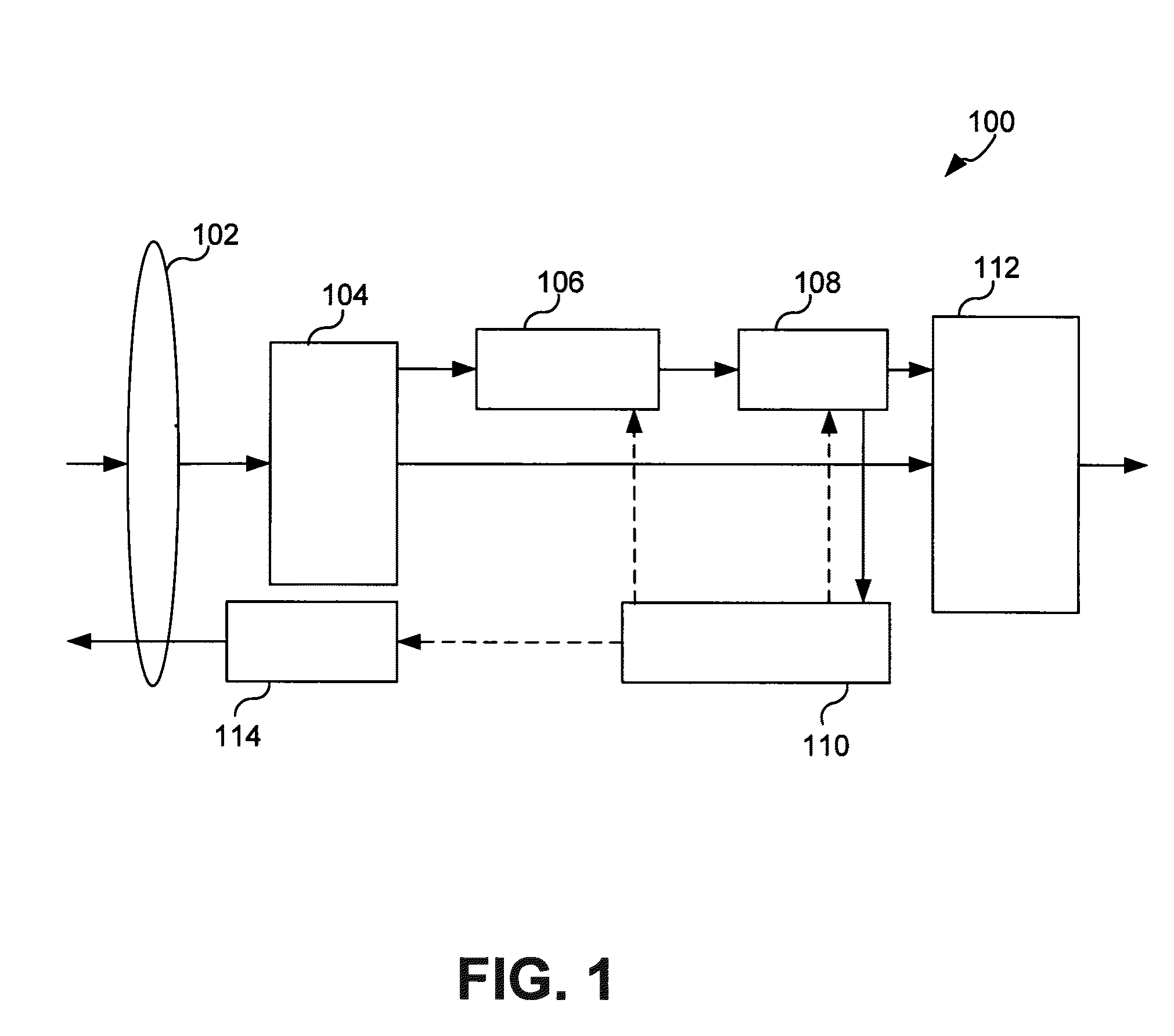
[0037]FIG. 1 is a schematic block diagram of an imaging system for providing resolution on demand in accordance with the present invention.

[0038]Referring now to FIG. 1, the imaging system for providing resolution on demand in accordance with the first embodiment includes an opto-mechanical imaging system 102, a spectral selector 104, a focal plane 106, a readout buffer 108, a cueing controller 110, a data combiner 112, and an illuminator 114.

[0039]The opto-mechanical imaging system 102 receives and relays upwelling radiation from a scene to the spectral selector 104. One of ordinary skill in the art would understand that the opto-mechanical imaging system 102 may be implemented in various ways, using materials and components based on the system's requirements. For example, the materials and components of the opto-mechanical imaging system 102 may be suitable to receive and relay upwelling radiation in the UV, VIS, NIR, PAN, MWIR, LWIR, LSWIR and / or USWIR wavebands of the spectrum (...

third embodiment

[0047]Referring still to the cueing controller 110 in FIG. 1, the cueing controller 110 controls operation of the illuminator 114. For example, the illuminator 114 is a laser or multiple lasers at different wavelengths. The illuminator 114 illuminates regions of interest of the scene to provide additional signal level at shorter wavelengths to improve spatial resolution at a minimum signal to noise ratio. In other words, the illuminator 114 illuminates each of the regions of interest that do not have sufficient ambient signal level to generate a useful image frame. For example, the ambient signal level is compared with a respective threshold of a plurality of thresholds (for each of the regions of interest) and the cueing controller 110 commands the illuminator 114 to illuminate the regions of interest that are at or below the corresponding threshold. As is described in greater detail with respect to a third embodiment illustrated in FIG. 3, the cueing controller 110 generates the m...

second embodiment

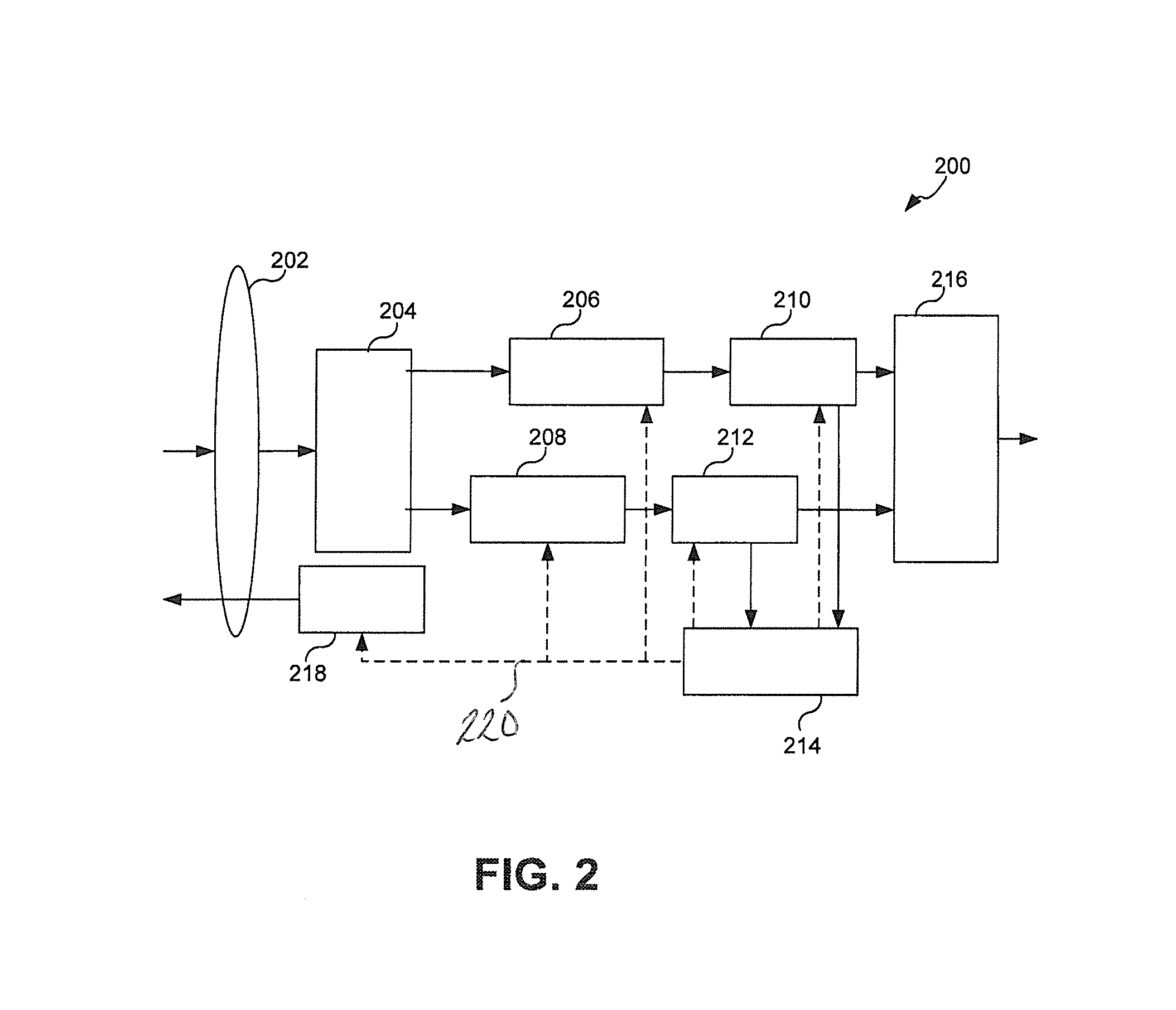
[0051]FIG. 2 is a schematic block diagram of an imaging system for providing resolution on demand in accordance with the present invention.

[0052]Referring now to FIG. 2, the imaging system 200 of FIG. 2 differs from the imaging system 100 of FIG. 1 in that the imaging system 200 includes a first focal plane 206 and a second focal plane 208, and a first readout buffer 210 and a second readout buffer 212. Rather than relying solely on the spectral selector 104 to filter and pass through specified wavebands to the focal plane 106, as in FIG. 1, the spectral selector 204 includes a dichroic beam splitter, configured to send all light with wavelengths above a specific threshold to the first focal plane 206 (e.g., above 1.0 μm). For example, wavelengths from 1.0 and up are made to impinge on the first focal plane 206, and wavelengths from about 1.0 and below are made to impinge on the second focal plane 208. The spectral selector 204 may further include a second level spectral selector fo...


PUM


Abstract

A method samples a first spectral band to obtain an initial image frame, determines at least one region of interest of the scene from the initial image frame, each of the at least one region of interest associated with a mean signal level, illuminates the at least one region of interest with at least one illuminator when the mean signal level of the at least one region of interest is at or below a respective threshold of a first plurality of thresholds, the at least one region of interest being illuminated in accordance with a power threshold indicating a minimum illuminator power and agility necessary to illuminate the at least one region of interest, collects at least one image frame in at least one sub-band of a second spectral band, and generates at least one image to be displayed from at least the at least one image frame.

Description

BACKGROUND[0001]1. Field of the Invention[0002]The present invention relates to an imaging system and method for providing resolution on demand.[0003]2. Description of Related Art[0004]Imaging systems have been widely used to image objects at long distances using telescopes sensitive to various portions of the spectrum.[0005]A fundamental issue regarding such imaging systems is obtaining high-resolution imagery. Resolution may be expensive to obtain or dangerous to collect, requiring large telescopes and / or close proximity to a potential threat. Generally, imaging systems attempt to provide the best spatial resolution possible given the inherent limitations of imaging optics and receiver technology. The spatial resolution inherent to an image collected by a given size telescope (e.g., based on aperture size) is determined by several factors including the wavelength of collected radiation, the dimensions of other apertures in the collection system including pixel aperture, geometric ...

Claims


Application Information

Patent Timeline
Patent Type & Authority Patents(United States)
IPC IPC(8): G06K9/32G06K9/36G06K9/38H04N5/30H04N5/335
CPCG01J3/2823G01S17/895G06T5/50H04N5/2256H04N5/23232H04N5/235H04N5/2354H04N9/045G06T2207/20221G01S17/90H04N23/56H04N23/951H04N23/70H04N23/74H04N23/84
Inventor ROBINSON, IAN S.
Owner RAYTHEON CO
Why Eureka
Try Eureka