Portable electronic device

a technology of electronic devices and covers, which is applied in the direction of telephone set construction, substation equipment, interconnection arrangements, etc., can solve the problems of insufficient operating power and user inconvenience, and achieve the effect of convenient transportation

Inactive Publication Date: 2006-01-31
NOKIA MOBILE PHONES LTD
View PDF12 Cites 27 Cited by
  • Summary
  • Abstract
  • Description
  • Claims
  • Application Information

AI Technical Summary

Benefits of technology

[0015]Preferably, the user interface has two configurations, a compacted configuration whereby the moveable element is in the first position and an expanded configuration whereby the moveable element is in the second position. Advantageously, when the user interface is in the compacted configuration, the device may readily be transported. When in the expanded configuration the user interface of the device may readily be used.
[0016]Preferably, the motor is connected to said moveable element using the gear and a rotating element with means for limiting the maximum force which the motor is subject to. The transmission between at least two parts in the transmission chain is based on a frictional contact in order to allow the motor to continue to run even when movement of the moveable element is prevented. In this way, the motor and the transmission components are not subject to excessive stresses. This limitation of the maximum force protects the motor and the transmission components.

Problems solved by technology

Since this is a manual action, it may become annoying to the user if it must be repeated numerous times a day, for example in the case of a mobile telephone, whenever the telephone rings.
Therefore, if the power provided by the battery supply falls to too low a level, insufficient operating power may be available to move a carriage for transporting a CD.

Method used


Image

  • Portable electronic device
  • Portable electronic device
  • Portable electronic device

Examples


Embodiment Construction

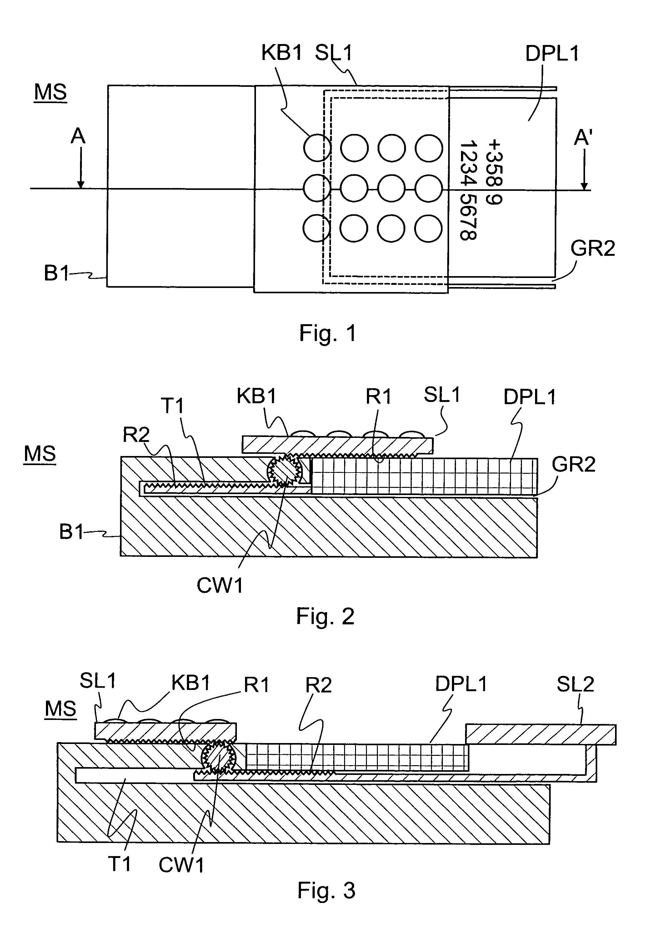
[0033]FIG. 1 shows a plan view of a mobile telephone MS according to the invention. The telephone comprises a body B1 having, at one of its ends, a space GR2 defined by side walls. The space GR2 occupies almost the complete width of the telephone. A display DPL1 is located in the space GR2. The display DPL1 is partially covered by a first slideable cover SL1. The first slideable cover SL1 comprises a keyboard KB1.

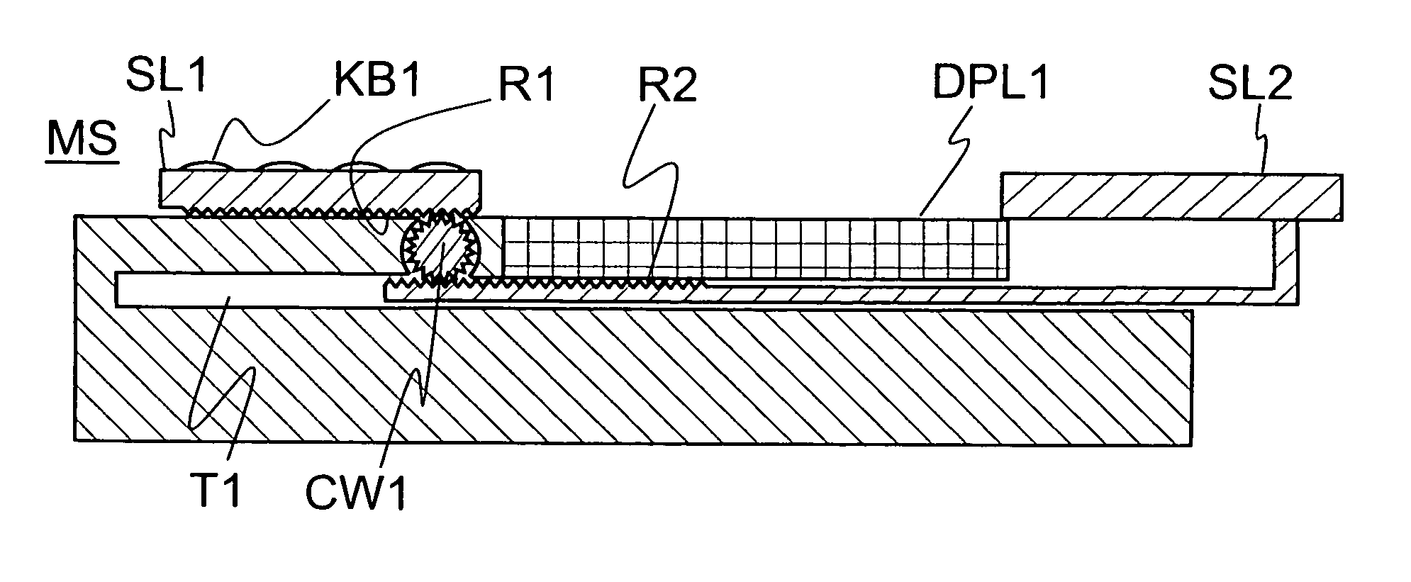
[0034]FIG. 2 shows a sectional view of the mobile telephone MS of FIG. 1 taken along line A–A′. Interior detail of the body B1 can now be seen. A rotatable toothed wheel CW1 is located in the body and is in contact with a bottom surface of the first slideable cover SL1. The bottom surface of the first slideable cover SL1 has a track which carries teeth which engage with the teeth of the toothed wheel CW1 so that the toothed wheel CW1 moves the slideable cover when it rotates. The display DPL1 is also slideable. A tunnel-like space T1 is provided below the toothed wheel CW1 ...


PUM


Abstract

A portable electronic device (MS) has a user interface (DPL1) that is protected by a motorized slide (SL1). The device has a first slide (SL1) which is moveable between positions in which it protects and exposes the user interface (DPL1). The slide is driven by an epicyclical gear which is, in turn, driven by an electrical motor. The epicyclical gear gears down a rotational speed provided by the motor into a rotational speed that is suitable for driving the slide.

Description

FIELD OF THE INVENTION[0001]This invention relates to electronic devices having covers and is particularly, but not exclusively, related to slideable covers to protect a user interface.BACKGROUND OF THE INVENTION[0002]Many electronic devices are equipped with a user interface comprising operating keys, a display or both. It is known to provide a slideable cover to protect such a user interface against damage, accidental activation and dust. Alternatively, it may be desirable to conceal the keys or some or all of the display for aesthetic reasons.[0003]In hand held or portable electronic devices, such a slideable cover is usually moved by a user pushing and pulling it back and forth. Since this is a manual action, it may become annoying to the user if it must be repeated numerous times a day, for example in the case of a mobile telephone, whenever the telephone rings. To mitigate this problem certain handheld devices are provided with a spring-loaded mechanism to open the slideable c...

Claims


Application Information

Patent Timeline
Patent Type & Authority Patents(United States)
IPC IPC(8): H04M1/00H04B1/38H04M1/02H04M1/724
CPCH04M1/0237H04M1/0247H04M1/72519H04M1/724
Inventor EROMAKI, MARKO
Owner NOKIA MOBILE PHONES LTD
Why Eureka
Try Eureka