Method and apparatus for evacuation of root canal

a root canal and apparatus technology, applied in the field of endodontics, can solve problems such as treatment complications

Active Publication Date: 2006-02-14
ORMCO CORP
View PDF4 Cites 55 Cited by
  • Summary
  • Abstract
  • Description
  • Claims
  • Application Information

AI Technical Summary

Benefits of technology

The invention solves issues where there was insufficient delivery of liquid to the end of a dental canal during cleaning procedures, leading to incomplete cleaning and potential health risks. A new device called a microaspirator is introduced that removes debris from the canal while applying negative pressure at the same time. This allows for better distribution of liquid throughout the entire canal without damaging or entering surrounding tissues.

Problems solved by technology

The technical problem addressed in this patent text is how to effectively flush debris and necrotic material from the root canal of a tooth without accidentally forcing the irrigant into the periapical tissue and risking post-treatment pain and complications. Existing techniques such as using small needles or an instrument to force the irrigant through a zone between the apex and needle tip are not completely effective and can result in a devoid area or zone between the apex and needle tip devoid of irrigant.

Method used


Image

  • Method and apparatus for evacuation of root canal
  • Method and apparatus for evacuation of root canal
  • Method and apparatus for evacuation of root canal

Examples


Embodiment Construction

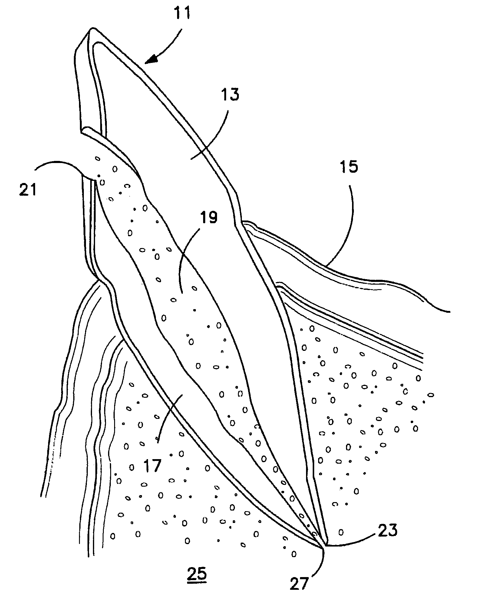
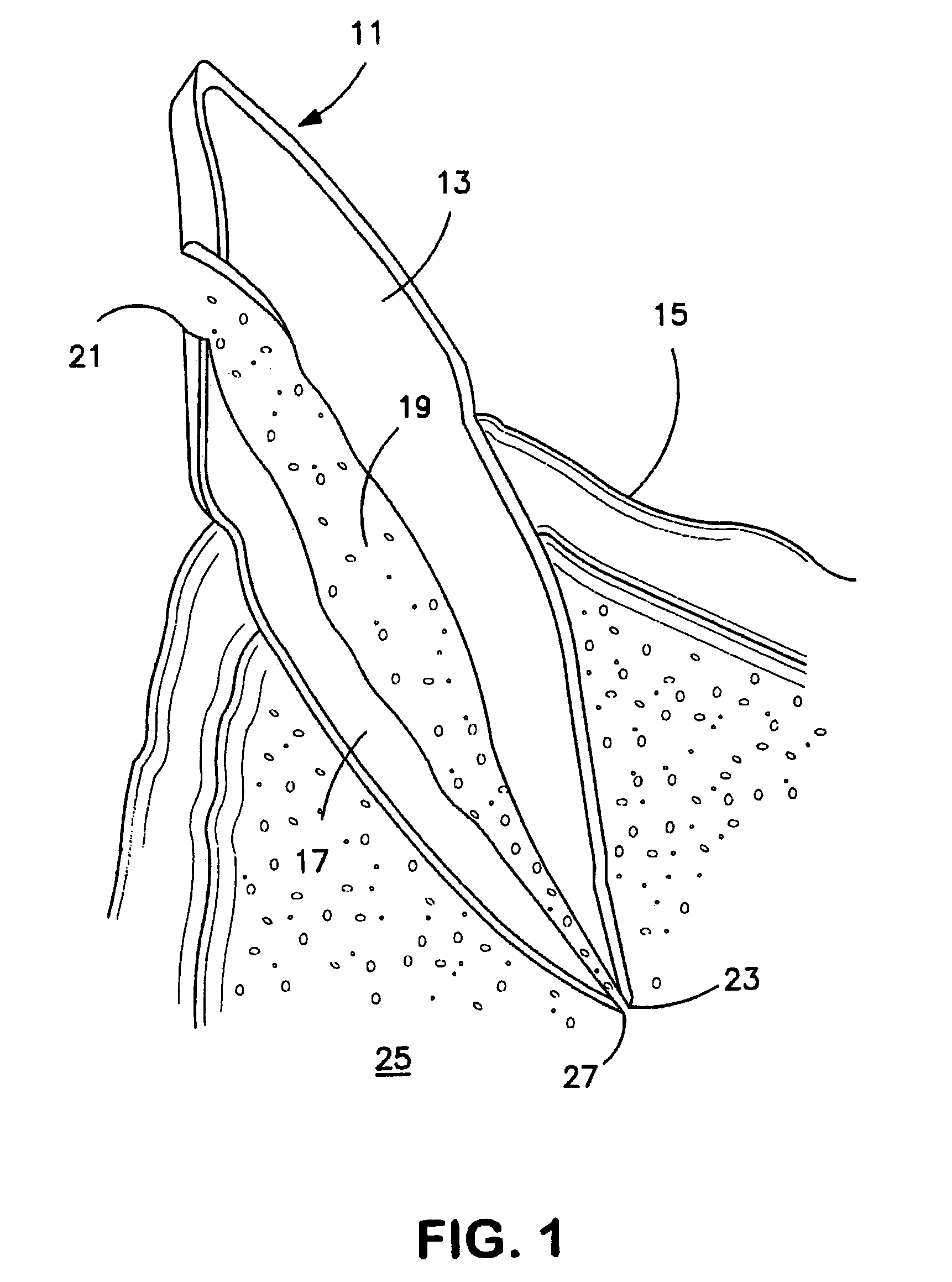
[0015]FIG. 1 illustrates a cutaway portion of a human tooth 11 as it may appear after a portion of a root canal procedure has been completed, namely wherein as much of the pulp material as is possible has been removed by instrumentation. The tooth 11 includes a crown portion 13 which is generally the exterior portion extending past gums 15. The interior portion of the tooth extending past the other side of gums 15 is referred to as the root 17. In approximately the middle of the root extending almost the entire length of the root is the root canal 19 which extends from one end 21 near the crown portion of the tooth to an apex 23 at the tip of root 17. As shown in FIG. 1, the non-visible portion of tooth 11 extending past gums 15 is surrounded by periapical tissue 25.

[0016]Of course, prior to the initiation of the root canal procedure, the apical foramen 27 located at or very near the root apex 23 is the only opening into the root canal.

[0017]After the instrumentation phase of the ro...


PUM


Abstract

After the working of a root canal by instruments to remove material and shape the walls of the canal, a microaspirator is inserted into the canal extending to about 5 mm from the apex and a vacuum is applied which sucks up some of the debris in the canal. Then a tube is inserted in the exposed opening of the canal with the vacuum still applied. Irrigant is supplied by the needle by an opening in the needle, but not under pressure. As the irrigant is supplied, it is drawn down to end of the aspirator by the vacuum which exists in the canal and up into the aspirator. The aspirator is removed and a second, smaller aspirator with a hole in its wall near its sealed end is inserted into the canal until it almost reaches the apex.

Description


Claims


Application Information

Patent Timeline
Owner ORMCO CORP
Why Eureka
Try Eureka