Hose and wand assembly

a technology of hoses and wands, applied in the direction of suction hoses, suction handles, cleaning equipment, etc., can solve the problems of inconvenient use, restrictions on manoeuvrability, cumbersome and difficult manoeuvrability, etc., and achieve the effect of removing unwanted stresses

Inactive Publication Date: 2006-02-21
DYSON TECH LTD
View PDF13 Cites 44 Cited by
  • Summary
  • Abstract
  • Description
  • Claims
  • Application Information

AI Technical Summary

Benefits of technology

[0006]It is an object of the present invention to provide a hose and wand assembly for a domestic appliance in which the manoeuverability is improved. It is a further object of the invention to provide a hose and wand assembly for a domestic appliance which, in use, reduces the loads and stresses applied to the user's hand.
[0008]By coupling the rigid wand portion to the flexible hose portion in a manner which allows swivelling about the longitudinal axis of the rigid wand portion, many of the stresses developed within the flexible hose portion during normal use of the hose and which are transmitted to the rigid wand assembly are eliminated. The flexible hose portion is able to swivel with respect to the rigid wand portion in response to any torsional stresses developed so that the stresses which would otherwise be transmitted to the wand are reduced or eliminated. In this way, the user of the domestic appliance is not required to apply physical forces to overcome the torsional stresses which might otherwise be developed. The position of the tool is thereby easier to control and the manoeuverability of the tool over the surface to be cleaned is improved.
[0009]By supporting the end portion of the hose at a position upstream of the outlet, the hose is rotatably coupled to the wand. This significantly reduces the proportion of the weight of the hose which is borne by the connection between the outlet of the hose and the wand. This allows the hose to rotate more freely with respect to the wand and also reduces the likelihood of the seal at the outlet from becoming damaged.
[0011]These improvements to the conventional hose and wand assembly have particular application to domestic appliances, specifically vacuum cleaners. They have particular benefits for elderly and disabled users. However, by eliminating unwanted stresses which might otherwise be applied to a user's hand and wrist, the improvements can also be beneficial to all users.

Problems solved by technology

A difficulty associated with conventional hose and wand assemblies is that they can be cumbersome and difficult to manoeuvre, particularly when accessing restricted areas and when the hose becomes distorted due to an excessive amount of twisting.
In order to provide sufficient durability, the flexible hose therefore has to be made of a durable material and this can result in the hose being relatively heavy which inevitably causes some restrictions to the manoeuverability of the hose and wand assembly and / or the floor tool carried thereby.
A further difficulty with conventional hose and wand assemblies is that, in order to achieve good pick-up results, the cleaning tool must be pressed firmly to the floor or carpet.
This means that the hose, which can be bulky and / or heavy, must be lifted further off the ground which is inconvenient for the user and adds to the load and stresses acting on the user's hand and wrist.

Method used


Image

  • Hose and wand assembly
  • Hose and wand assembly
  • Hose and wand assembly

Examples


Embodiment Construction

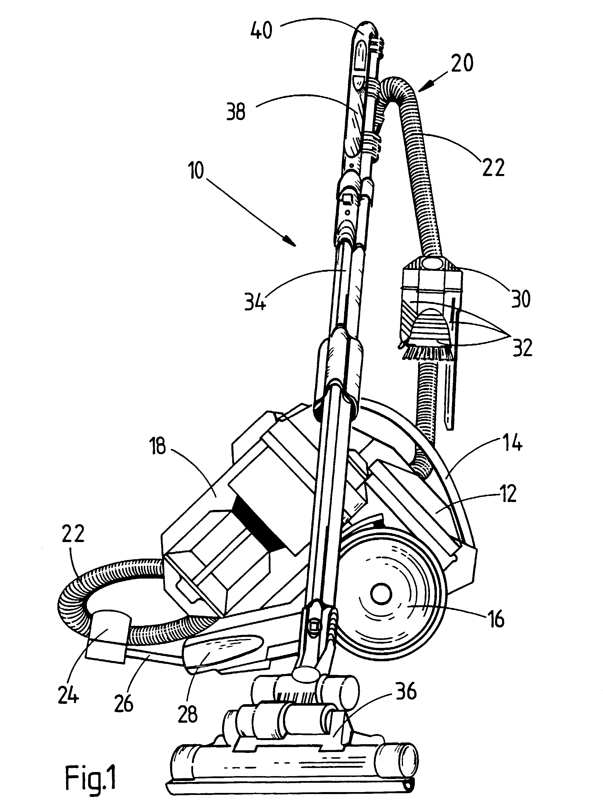
[0017]The vacuum cleaner 10 illustrated in FIG. 1 comprises a main body 12 having a handle 14, supporting wheels 16 and separating apparatus 18. The separating apparatus 18 illustrated in this embodiment takes the form of a cyclonic separating device of a type known to be used in domestic vacuum cleaners. A full description of this type of separating apparatus can be found in EP 0 042 723B but this arrangement does not form part of the present invention. Indeed, the separating apparatus 18 illustrated in FIG. 1 could quite adequately be replaced by the more conventional bag-type separator or other separation apparatus if desired. The main body 12 also houses other essential components of a vacuum cleaner; namely, an electrically operated motor, a fan driven by the motor and arranged to develop suction within the separating apparatus 18, filters designed and located so as to protect the fan and motor, an electric cable for connection to a mains supply and an on / off control switch. Al...


PUM


Abstract

A hose and wand assembly for a domestic appliance includes a flexible hose portion, a rigid wand portion and a handgrip portion. The hose terminates in a curved end portion which couples to the wand in such a manner that the hose is able to swivel about the longitudinal axis of the wand. The end portion has an outlet which communicates with the interior of the wand. A support is located on the outer wall of the end portion upstream of the outlet. The support is capable of pivotal movement about the longitudinal axis of the rigid wand portion. The hose is also rotatable with respect to the wand about the longitudinal axis of the hose.

Description

FIELD OF THE INVENTION[0001]The invention relates to a hose and wand assembly for a domestic appliance, particularly but not exclusively for a vacuum cleaner.BACKGROUND OF THE INVENTION[0002]Cylinder vacuum cleaners generally comprise a main body containing separating apparatus for separating dirt and dust from an airflow. The airflow is introduced to the main body via a hose and wand assembly to the distal end of which is normally attached a cleaning tool. The hose and wand assembly comprises a rigid wand portion which is attached to the main body via a flexible hose. The flexible hose is commonly connected to the wand portion by way of a rotatable coupling which allows the flexible hose to rotate about its own axis whilst remaining coupled to the rigid wand portion. A handgrip portion is commonly located at the end of the rigid wand portion remote from the cleaning tool and adjacent the flexible hose. By means of the gripping portion, the cleaning tool is manoeuvered over the surf...

Claims


Application Information

Patent Timeline
Patent Type & Authority Patents(United States)
IPC IPC(8): A47L9/32A47L9/24
CPCA47L9/327A47L9/242
Inventor NIGHY, RICHARD JOHN
Owner DYSON TECH LTD
Why Eureka
Try Eureka