Backbone motorcycle frame having a partial cradle which supports a rear portion of a unitized engine and transmission and to which foot peg assemblies are bolted

Inactive Publication Date: 2010-03-18
GOODWIN GARY A
View PDF16 Cites 7 Cited by
  • Summary
  • Abstract
  • Description
  • Claims
  • Application Information

AI Technical Summary

Benefits of technology

[0012]Footpeg mounts are attached to the partial rear cradle via a unique attachment system. Each end of the transverse bar or tube of the lower brace extends through the C-shaped box section member to which it is welded. If a transverse bar rather than a transverse tube is employed in the lower brace, both ends of the bar are axially drilled to create a cylindrical recess that will accept a cylindrical stud. Threaded attachment holes are provided on opposite sides of each cylindrical recess. A footpeg mount includes a footpeg socket to which the actual footpeg attaches with a hinge pin, a mounting plate having a pair of aperture which align with the threaded attachment holes on opposite sides of each cylindrical recess, and a stalk that interconnects the footpeg socket and the mounting plate. A cylindrical mounting stud, which extends from the opposite side of the attachment plate, is axially aligned with the stalk. In order to install the footpeg mount, the mounting stud is inserted within the cylindrical recess and the mounting plate is secured to an associated C-shaped box section member with a pair of attachment bolts. Stresses and loads applied to the footpegs are transferred to the transverse bar or tube, thereby greatly reducing stresses and loads applied to the mounting plate and attachment bolts. A footpeg mount can be easily replaced by simply removing the two attachment bolts, removing the old footpeg mount and installing a new one in its place.
[0013]The frame of the present invention has a number of advantages over those of the prior art, and over the frame of Brown, et al. in particular. Firstly, the lower portion of the frame, including the lower engine mount and footpeg mounts, are integral with the rest of the frame. Only the upper engine mount, which is lightly stressed, is bolted to the frame so that it can be removed in order to remove the engine. Secondly, the frame is fabricated completely from steel, and does not require machined aluminum or steel parts for the lower engine mount and footpeg mounts. This feature reduces both manufacturing cost and weight. Thirdly, the rear engine mount is integral and rigidly affixed to the frame, as it does not use the floating arrangement of Brown, et al.

Problems solved by technology

If the nuts on the threaded studs become loose, high impact forces will be applied to the threaded studs through the nuts.
If a catastrophic failure of the footpeg mounting hardware were to occur, the rider would fall and his feet would strike the ground, causing him to fall face first on top of the motorcycle.
In such a situation, a total loss of control would be likely.
Given the fact that many of these small displacement motorcycles are raced, a failure of the footpeg assembly will endanger not only the rider, but also nearby competitors.
A less likely scenario is that the mounting points, from which the engine / transmission unit is suspended from the frame, will fail, resulting in the engine hitting the ground.
Such an event could also be dangerous, and would almost certainly doom the engine / transmission case to the scrap bin.
A drawback to this modified frame design is that the footpeg assembly cannot be replace without completely removing the engine from the frame.
As there must be a certain amount of play between the spacer and the bolt which secures the rear suspension swing arm to the main frame portion, the connection of the engine to the frame through this rear mount can never be completely rigid.
There are a number of disadvantages associated with the frame design of Brown, et al.
Firstly, Brown's footpeg mounting bracket is expensive to manufacture and will never provide the rigidity, strength and lightness of weight that welded fabrication can provide.
Secondly, in order to remove the engine if the footpeg mounting bracket is welded to the main portion of the frame, the footpeg mounting bracket would need to be cut out of the frame.
Third, the floating rear engine mount reduces the structural integrity of the engine / transmission mounting system.

Method used


Image

  • Backbone motorcycle frame having a partial cradle which supports a rear portion of a unitized engine and transmission and to which foot peg assemblies are bolted
  • Backbone motorcycle frame having a partial cradle which supports a rear portion of a unitized engine and transmission and to which foot peg assemblies are bolted
  • Backbone motorcycle frame having a partial cradle which supports a rear portion of a unitized engine and transmission and to which foot peg assemblies are bolted

Examples


Embodiment Construction

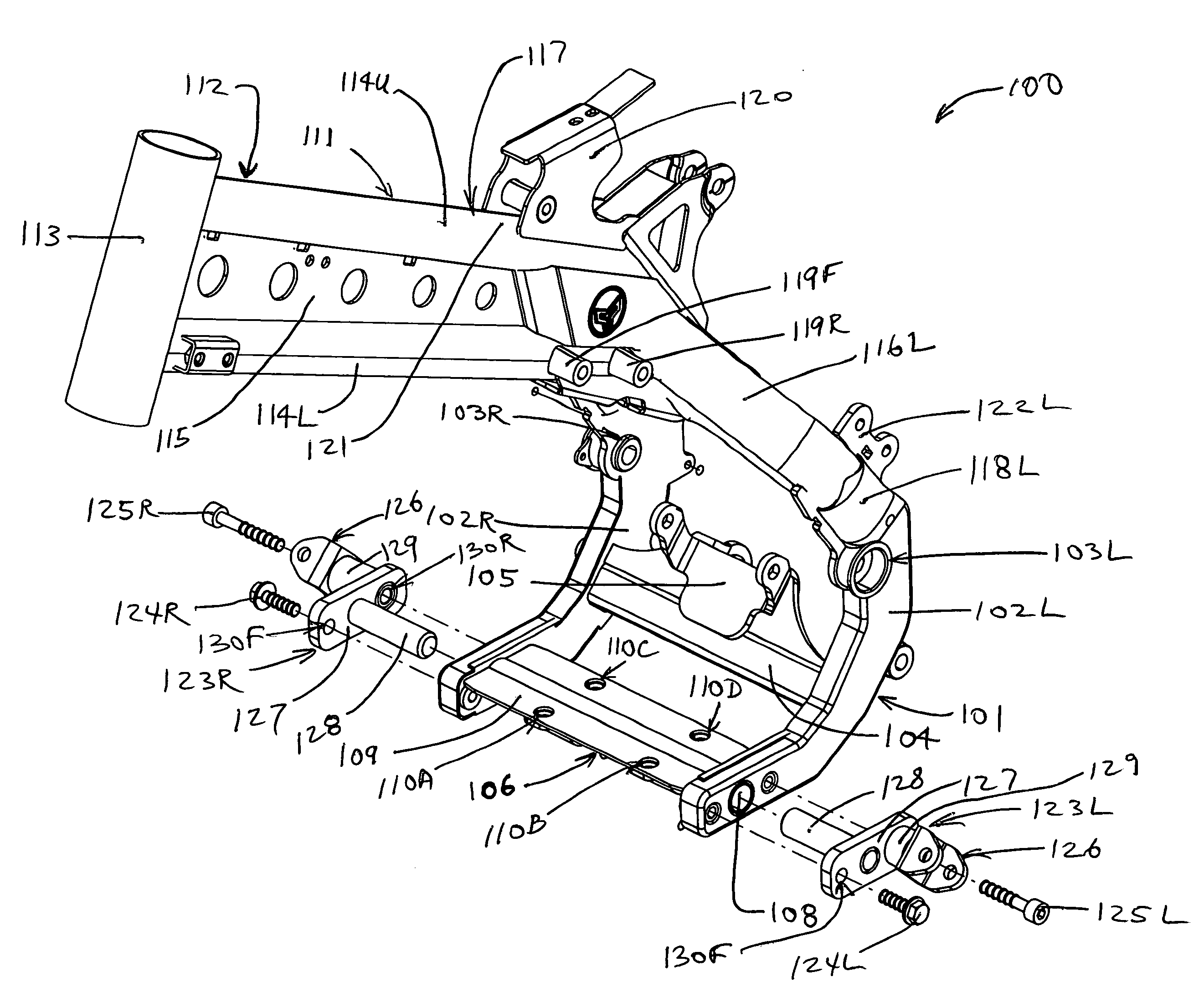
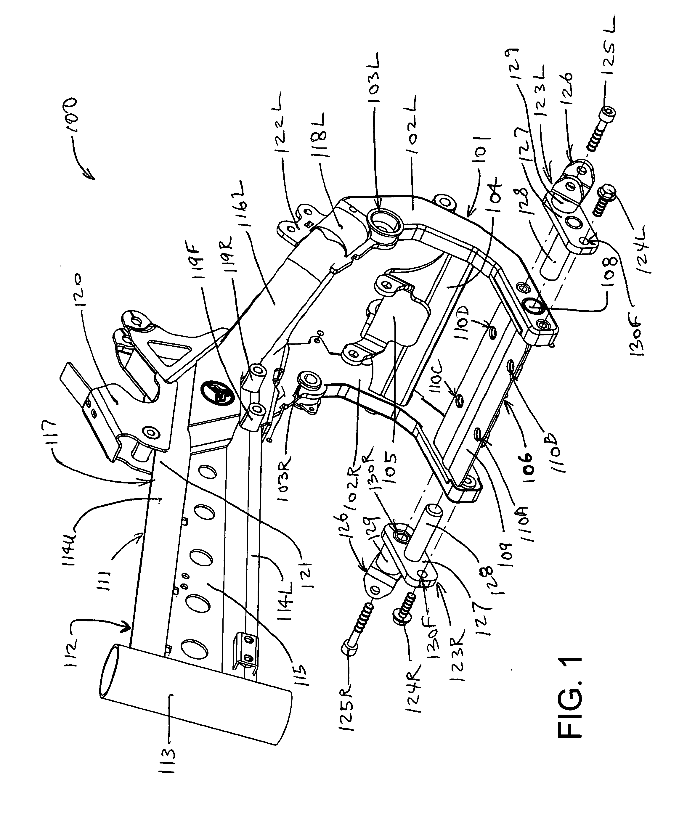
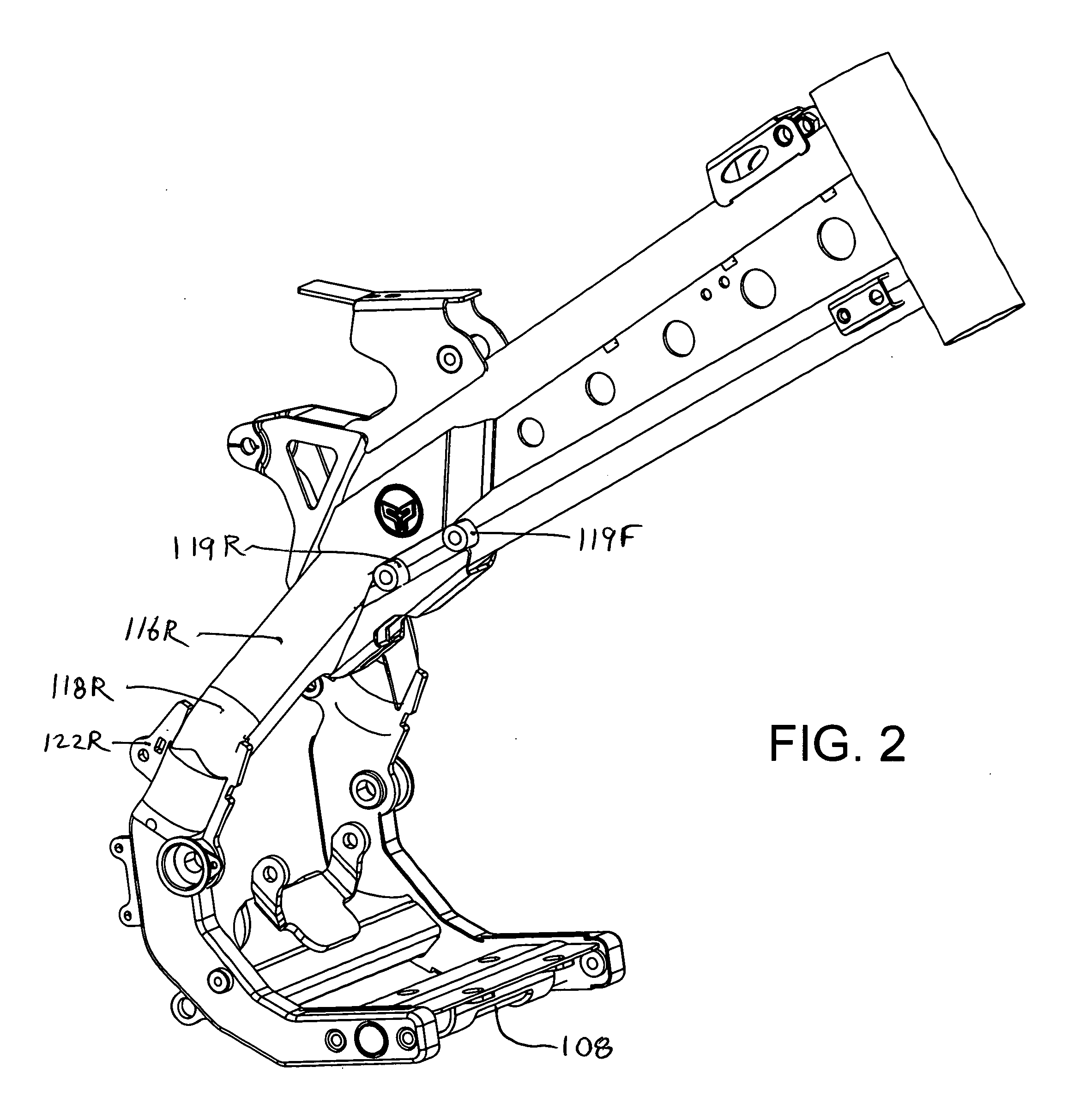
[0029]The invention will now be described with reference to the attached drawing FIGS. 1 through 15. It should be understood that although the drawings are intended to be merely illustrative, a reasonable attempt has been made to provide drawings that are close to scale.

[0030]Referring now to FIGS. 1 and 2, the new backbone-type frame 100 of the present invention has a partial rear cradle 101 comprised of left and right, spaced-apart crescent, or C-shaped, box-section members 102L and 102R, respectively, which are fabricated primarily of stamped structural sheet metal, and which “cradle” opposite sides of a rear portion of a unitized horizontal single-cylinder engine / transmission unit (not shown). Each of the C-shaped box-section members 102L and 102R incorporates a rear swing arm attachment aperture 103L and 103R, and the swing arm (not shown in this view) is secured between the two apertures 103L and 103R with a swing arm pivot bolt (also not shown in this view). In addition, a re...


PUM


Abstract

The backbone-type frame has a partial rear cradle which includes spaced-apart left and right crescent-shaped, box-section members. A lower brace is welded to and interconnects the lower forward-extending portions of each C-shaped box-section member. The lower brace, which is securable to threaded apertures on the bottom of a unitized engine / transmission case, includes a transverse tube which extends through both box-section members, the tube having a cylindrical aperture on each end thereof. A footpeg mounting bracket having a mounting stud is bolted to each box-section member, with its mouting stud inserted within the cylindrical aperture of one end of the transverse tube or bar. The footpeg mounts are easily replaceable.

Description

[0001]This application has a priority date based on Provisional Patent Application No. 61 / 097,325, which has a filing date of Sep. 16, 2008, and bears the same title.BACKGROUND OF THE INVENTION[0002]1. Field of the Invention[0003]This invention relates to motorcycles and motorcycle frames and, more particularly, to backbone-type frames wherein a unitized engine and transmission assembly functions as a stressed structural member.[0004]2. Description of the Prior Art[0005]Modern motorcycles typically comprise the following components: a frame; a rear wheel coupled to the frame via a rear suspension assembly; a front wheel coupled to the frame via a front fork incorporating a front suspension system; a handlebar rigidly coupled to the front fork; a brake associated with each wheel; engine controls and a front brake control mounted on the handlebar; a unitized engine and transmission bolted to the frame; and a drive system coupling the transmission output to the rear wheel. As early mot...

Claims


Application Information

Patent Timeline
IPC IPC(8): B62M7/02
CPCB62K25/283B62K11/06B62K25/286
Inventor GOODWIN, GARY A.
Owner GOODWIN GARY A
Why Eureka
Try Eureka