Slidable vehicle seat provided with automotive electronic parts
- Summary
- Abstract
- Description
- Claims
- Application Information
AI Technical Summary
Benefits of technology
Problems solved by technology
Method used
Image

Examples
first embodiment
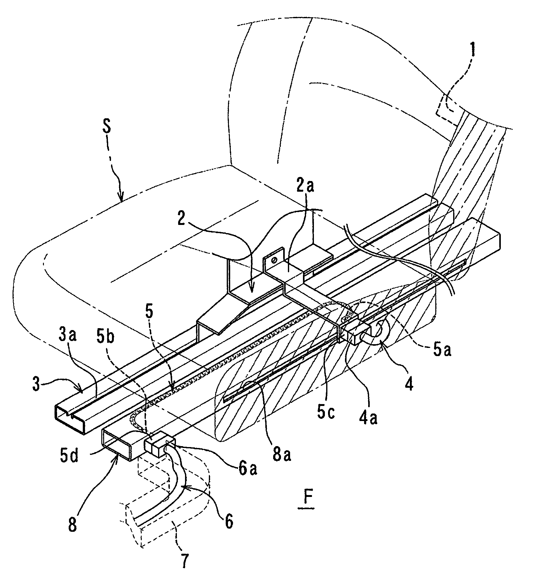
[0053]Referring to FIG. 1, there is illustrated the vehicle seat S (shown in phantom) provided with the automotive electronic parts 1 (only one automotive electronic component 1 is shown in FIG. 1), in accordance with the present invention. The vehicle seat S is adapted to be moved forward and rearward in a vehicle through a seat track mechanism. The seat track mechanism includes a pair of substantially parallel movable rails 2 (only one movable rail 2 is shown in FIG. 1) attached to a lower portion of the vehicle seat in slidable relationship with a pair of substantially parallel stationary rails 3 (only one stationary rail 3 is shown in FIG. 1) which are attached to a floor section F of the vehicle. Each of the stationary rails 3 has a longitudinally extending opening 3a through which a corresponding movable rail 2 is slidably combined with the stationary rail 3 and slid along.
[0054]The first electrical wiring means 4 which is led out of the automotive electronic parts 1 provided ...
second embodiment
[0082]Referring to FIGS. 22 and 23, there is illustrated a slidable vehicle seat according to the present invention. This embodiment is substantially similar to the example shown in FIG. 9 except that the housing means 8 comprises a longitudinal groove 800 formed in the floor section F of the vehicle. In this embodiment, the second electrical wiring means 5 shown in FIG. 7 is employed. However, the second electrical wiring means 5 shown in FIGS. 2, 11 and 12 may be employed. In FIGS. 22 and 23, components that are substantially similar to those of the vehicle seat shown in FIG. 9 are denoted by the same reference numerals. The description of them will not be repeated hereinafter.
[0083]As described above, the housing means 8 comprises the groove 800 formed in the floor section F of the vehicle. The groove 800 extends along the stationary rail 3. The second electrical wiring means 5 is movably housed within the groove 800. The sixth coupler 110b penetrates a side wall of the groove 80...
third embodiment
[0084]Referring to FIGS. 24–27, there is illustrated the present invention. In this embodiment, one of the above-mentioned constructions for connecting the first electrical wiring means of the automotive electronic parts via the second electrical wiring means to the third electrical wiring means connected to the power source is applied to a first bench-type rear seat S1 and a second bench-type rear seat S2 which is arranged in back of the first rear seat S1. Although the electrical wiring means connecting constructions are not shown in FIGS. 24–27, any one of the electrical wiring means connecting constructions discussed above can be employed. Therefore, the description of them will not be repeated hereinafter.
[0085]In the embodiment shown in FIGS. 24–27, each of the first and second bench-type rear seats S1, S2 is provided with automotive electronic parts (not shown). The rear seats S1, S2 are adapted to be moved forward and rearward in the vehicle through a seat track mechanism, a...
PUM
 Abstract
Description
Claims
Application Information
 - Generate Ideas
- Intellectual Property
- Life Sciences
- Materials
- Tech Scout
- Unparalleled Data Quality
- Higher Quality Content
- 60% Fewer Hallucinations
Browse by: Latest US Patents, China's latest patents, Technical Efficacy Thesaurus, Application Domain, Technology Topic, Popular Technical Reports.
© 2025 PatSnap. All rights reserved.Legal|Privacy policy|Modern Slavery Act Transparency Statement|Sitemap|About US| Contact US: help@patsnap.com