Portable electronic apparatus and a display control method

a technology of electronic equipment and control method, applied in the field of portable electronic equipment, can solve the problems of increased cost, poor user interface, and inability to provide a good visible pictur

Inactive Publication Date: 2006-02-21
INTELLECTUAL VENTURES HOLDING 81 LLC
View PDF11 Cites 72 Cited by
  • Summary
  • Abstract
  • Description
  • Claims
  • Application Information

AI Technical Summary

Benefits of technology

[0013]a memory having stored a plurality of touch patterns sensed by the first and second touch sensors and a plurality of display control programs for controlling the display device in a corresponding relationship.
[0014]According to one another aspect of the present inventi...

Problems solved by technology

Therefore, for example, in order to scroll up or down the displayed picture, parts to be used exclusively for scrolling purposes (a ring-like part rotatable by a finger, so-called “wheel”) are needed to thereby increase the cost.
In the touch screen, the display can be dama...

Method used


Image

  • Portable electronic apparatus and a display control method
  • Portable electronic apparatus and a display control method
  • Portable electronic apparatus and a display control method

Examples


first embodiment

(First Embodiment)

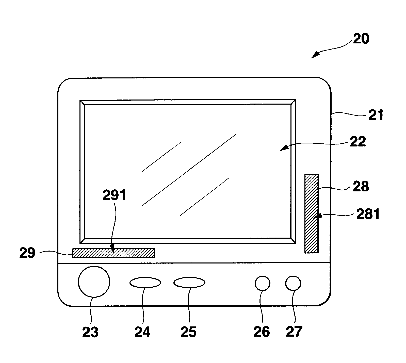
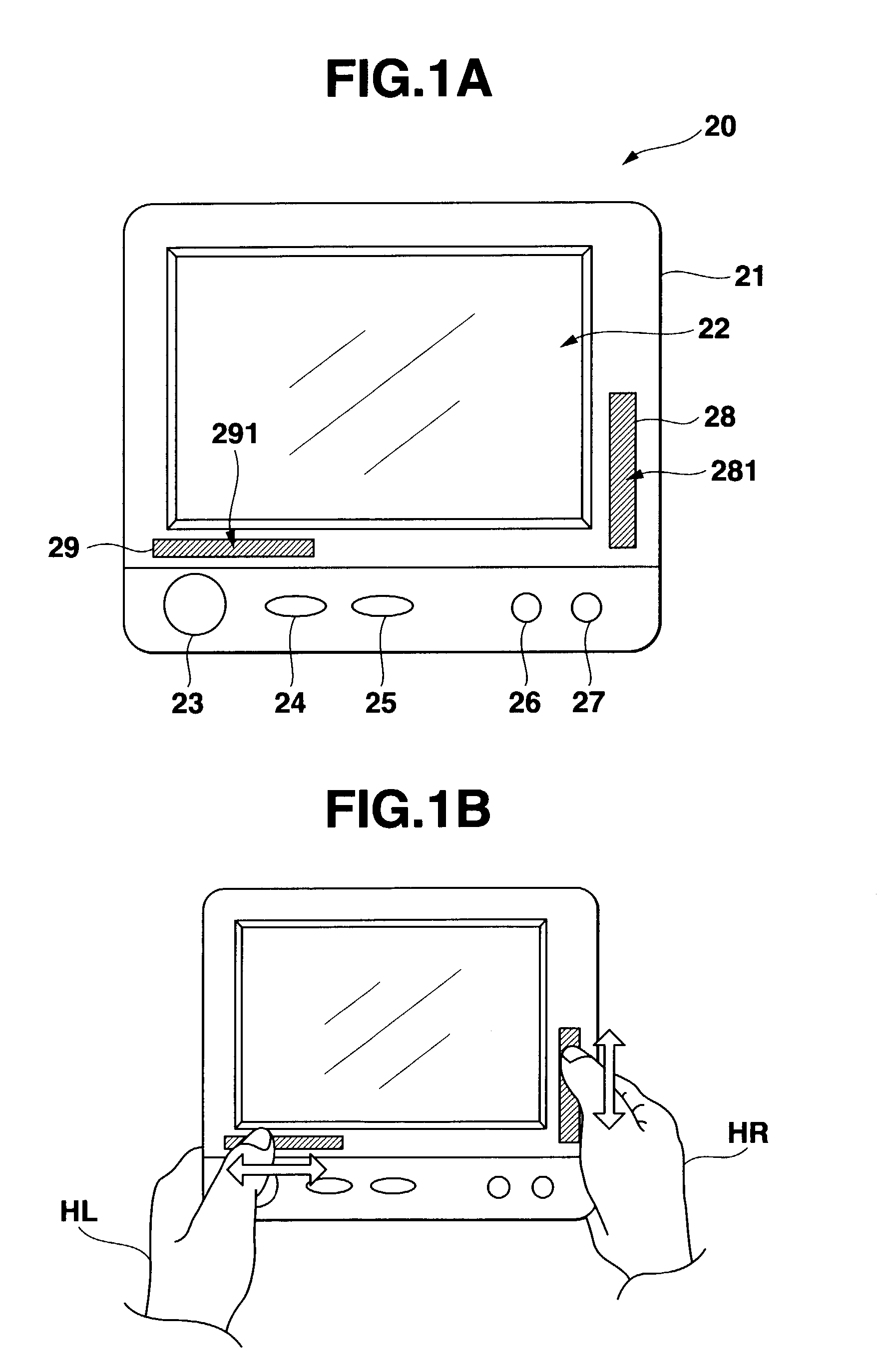
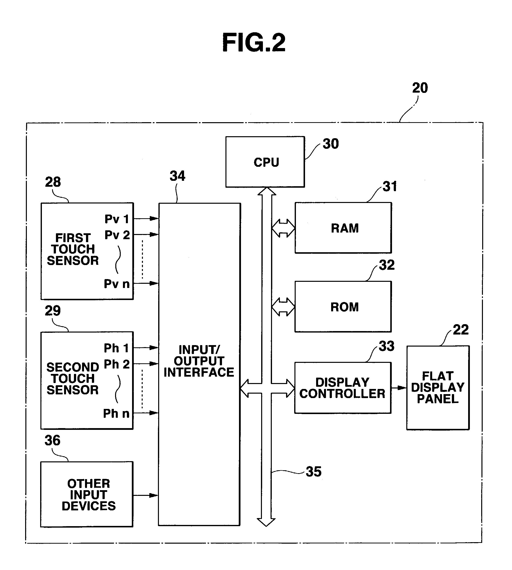
[0055]FIG. 1A is a front view of an electronic apparatus to which the present invention is applied. FIG. 1B shows a state in which the electronic apparatus is used. The electronic apparatus 20 has a portable thin body including a display screen integral therewith visible to a user while being held by both the hands HR, HL of the user. Disposed on a front of the device body 21 are a flat display panel 22 such as a LCD (Liquid Crystal Display) or an ELD (Electroluminescence Display), various operation buttons 23–27, a first touch sensor 28 and a second touch sensor 29 as elements unique to the present embodiment. The first and second touch sensors 28 and 29 have rectangular touch sensing sheets 281 and 291 on their fronts, respectively.

[0056]The first touch sensor 28 is preferably disposed at a position on the device front where when the device body 21 is held by both the hands of the user, the rectangular touch sheet 281 is easily manipulated vertically with a finge...

second embodiment

(Second Embodiment)

[0120]A second embodiment will be described next. The appearance and block diagram of an electronic apparatus 20 of the second embodiment and the structures of the first and second touch sensors 28 and 29 of the second embodiment are identical to those of the first embodiment shown in FIGS. 1–3, and further description and illustration thereof will be omitted.

[0121]FIG. 16 schematically illustrates a memory map of ROM 32, which includes a storage area 32a for an operating system, a storage area 32b for application programs, and a storage area 32d for a program to realize processes unique to the second embodiment (hereinafter referred to as “automatic scroll program” for convenience of explanation).

[0122]FIG. 17 is a schematic flowchart of the automatic scroll program. A process represented by this flowchart is performed at predetermined intervals of time or in response to an interrupt corresponding to a touch on a rectangular touch sheet 281 of the first touch sen...

third embodiment

(Third Embodiment)

[0143]A third embodiment will be described next. The appearance and block diagram of an electronic apparatus 20 of the third embodiment and the structures of the first and second touch sensors 28 and 29 of the third embodiment are identical to those of the first embodiment shown in FIGS. 1–3, as in the second embodiment, and further description and illustration thereof will be omitted.

[0144]FIG. 25 is a block diagram of the embodiment that includes in a hardware part a vertical slide bar 400 (corresponding to the first touch sensor 28) and a horizontal slide bar 401 (corresponding to the second touch sensor 29), a touch count processor 402, a key code converter 403, a key code conversion table 404 and an application section 405 formed in a software part in a superordinate layer.

[0145]FIG. 26 is a flowchart of operation of the touch count processor 402. This flowchart starts up in response to an interrupt from the hardware part (the vertical or horizontal slide bar ...


PUM


Abstract

An electronic apparatus 20 is of a portable type and has a thin body integral with a display screen holdable by both hands HR, HL of a user for viewing purposes. Disposed on a front of the body 21 are a flat display panel 22 and various operation buttons 23–27, and first and second touch sensors 28 and 29. The first touch sensor 28 is disposed on the apparatus at a position where when the body 21 is held by both the hands of the user, a touch surface of the first sensor 28 is easily operated vertically by a finger of the user's right-hand HR whereas the second touch sensor 29 is disposed at a position where when the body 21 is held by both the hands of the user, its touch surface is easily operated horizontally by a finger of the user's left-hand HL.

Description

BACKGROUND OF THE INVENTION[0001]1. Field of the Invention[0002]The present invention relates to portable electronic apparatus.[0003]2. Background Art[0004]In electronic apparatus such as computers, various pointing devices have been used as input devices. A typical one of the pointing devices is, for example, a mouse that freely moves a cursor displayed on the display screen and performs a single or double clicks at the position of the cursor. Portable electronic apparatus have a “touch pad” or “touch screen” instead of the mouse (For example, Published Japanese Patent Application “H11-203046”, pages 3and 4, FIG. 4).[0005]The touch pads and touch screens have only a function to specify a coordinate position. In other words, they only substitute for the cursor-moving function of the mouse. Therefore, for example, in order to scroll up or down the displayed picture, parts to be used exclusively for scrolling purposes (a ring-like part rotatable by a finger, so-called “wheel”) are nee...

Claims


Application Information

Patent Timeline
IPC IPC(8): G09G5/00G06F1/16G06F3/033G06F3/0362G06F3/038G06F3/048
CPCG06F1/1626G06F1/169G06F3/04883G06F3/03547G06F2203/0339G06F2200/1614
Inventor IIZUKA, NOBUOFUKUSHIMA, TAKAYUKIMATSUNAGA, KAZUHISA
Owner INTELLECTUAL VENTURES HOLDING 81 LLC
Why Eureka
Try Eureka