
Appliance for vacuum sealing food containers

a vacuum sealing and food container technology, applied in the field of packaging systems, can solve the problems of less efficient drawing power or breakdown, liquid or other particles in the container may be ingested, damage to the vacuum source,

Inactive Publication Date: 2006-02-28
HOLMES GRP THE
View PDF598 Cites 79 Cited by
  • Summary
  • Abstract
  • Description
  • Claims
  • Application Information

AI Technical Summary

Benefits of technology

[0008]The above shortcomings and others are addressed in one or more preferred embodiments of the invention described herein. In one aspect of the invention, a system for evacuating containers is provided comprising a base housing and a recess defined within the base housing. A vacuum inlet port is within the recess and is in communication with a vacuum source located within the base housing. An inner door is hinged to the base housing and sized to cover the recess when in a closed position. An outer door having a heat sealing means mounted thereon is hinged to close over the inner door. A vacuum nozzle extends at least partially between the inner and outer doors and is in communication with the recess. The inner and outer doors cooperate to retain a flexible container therebetween and around the nozzle so that the nozzle is positioned for fluid communication with an inside of the container.

Problems solved by technology

A problem with many of these appliances is that as air is being removed from the bag or other suitable container, liquids or other particles in the container may be ingested into the vacuum source of the appliance.
Ingesting liquids or other particles into the vacuum source, which is typically an electric device, may damage the vacuum source, creating less efficient drawing power or a breakdown.
This is especially a problem when evacuating air from flexible containers containing liquidous food.
Another problem with many of these appliances is a lack of sufficient vacuum pressure within the appliance.
Prior art systems have lacked a vacuum source with enough power to draw a significant amount of air from a container.
An additional problem with many appliances is the inability to seal a container independently from the vacuuming process.

Method used


Image

  • Appliance for vacuum sealing food containers
  • Appliance for vacuum sealing food containers
  • Appliance for vacuum sealing food containers

Examples


Embodiment Construction

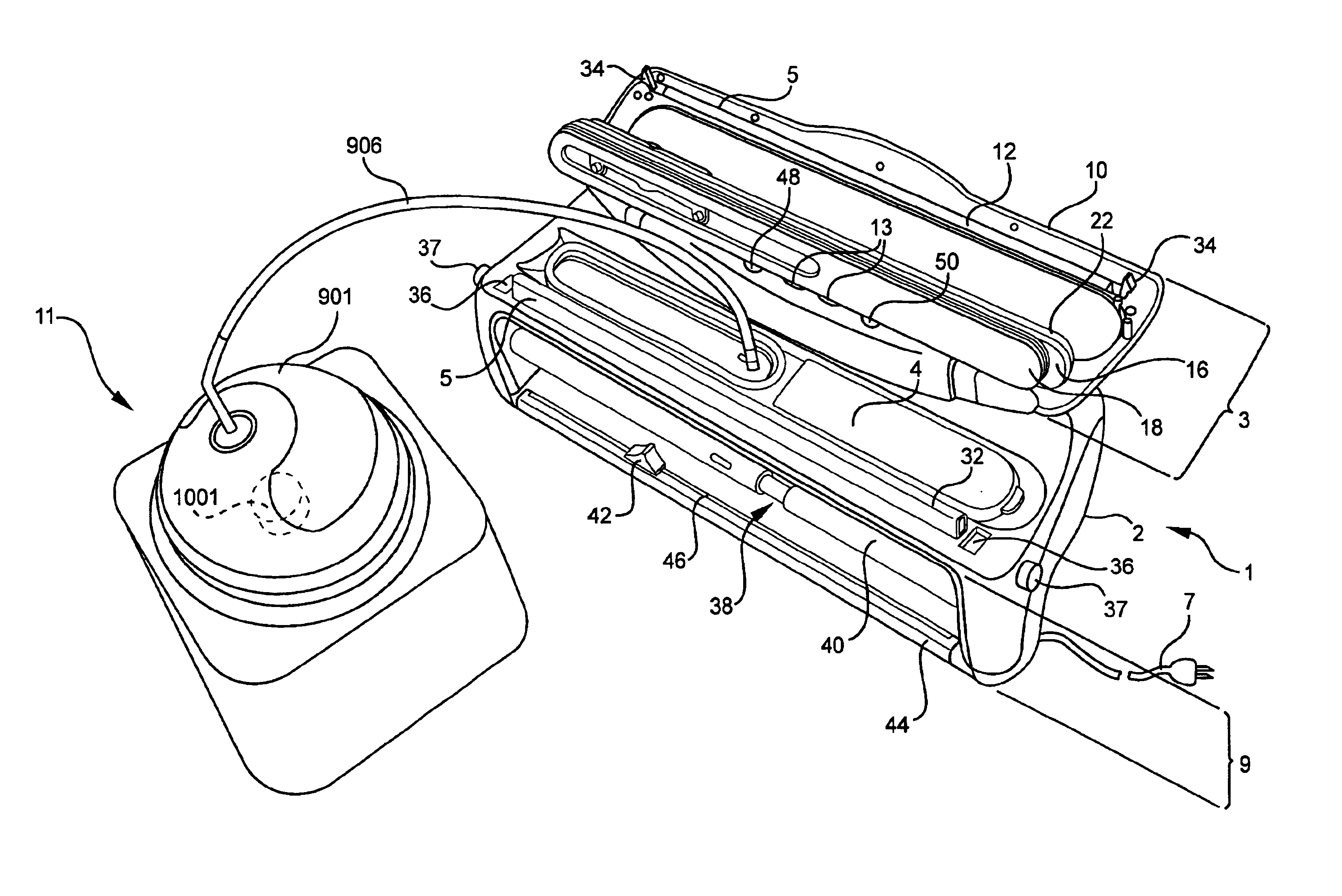
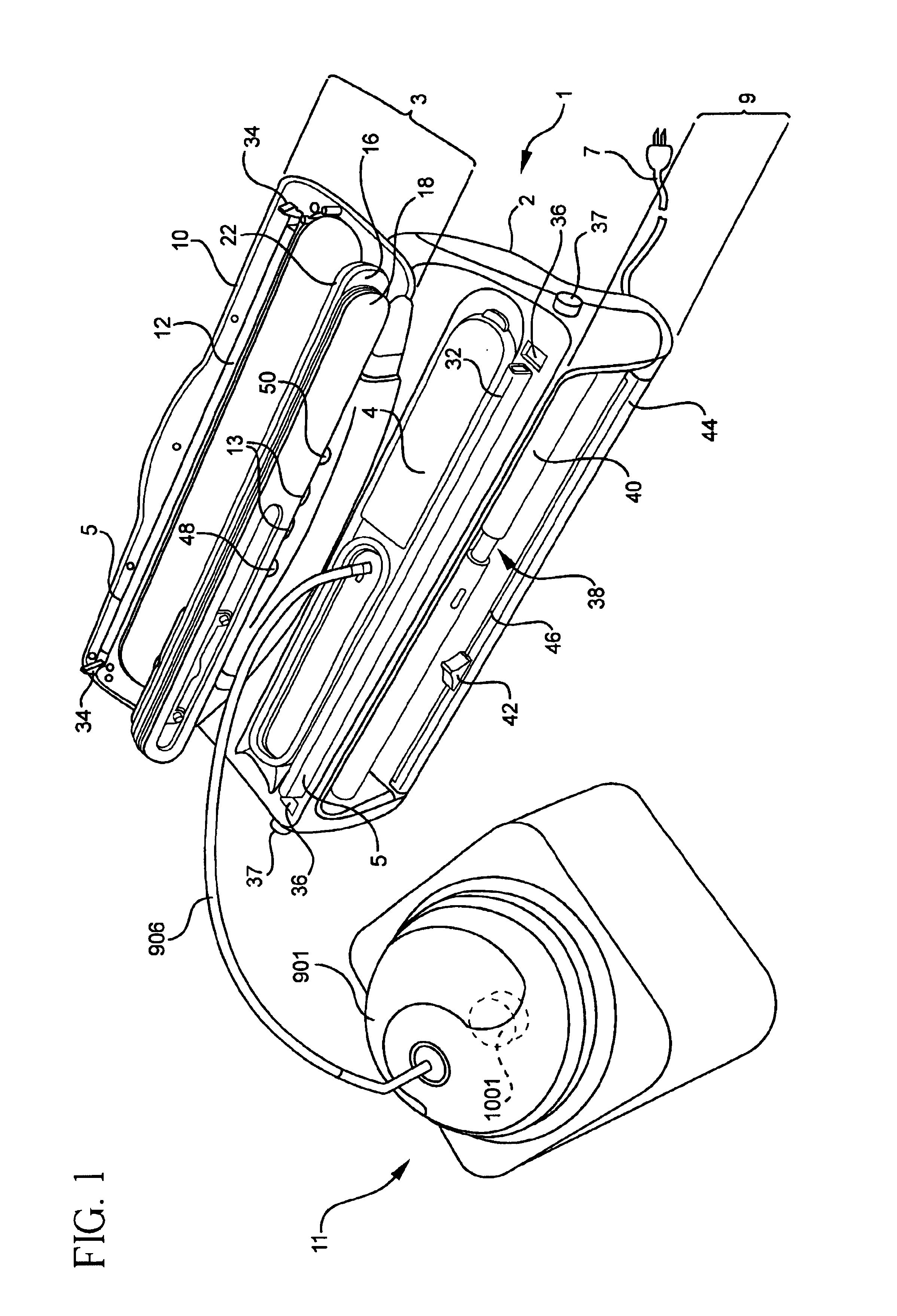
[0034]As shown in FIG. 1, this invention relates to a system for vacuum packaging or vacuum sealing containers. The basic components of the system are a vacuum sealing appliance 1, an adaptor 901, and canister lids implementing a canister lid valve assembly 1001. As shown in FIG. 2b, the vacuum sealing appliance 1 contains a vacuum source 15 and a control system 17 for the system implementing a pump 301 and a pressure sensor 501. As shown in FIG. 1, the vacuum sealing appliance 1 uses the vacuum source 15 to extract air from plastic bags and the adaptor 901 uses the vacuum source 15 to extract air from separate rigid containers such as mason jars or canisters using a canister lid valve assembly 1001.

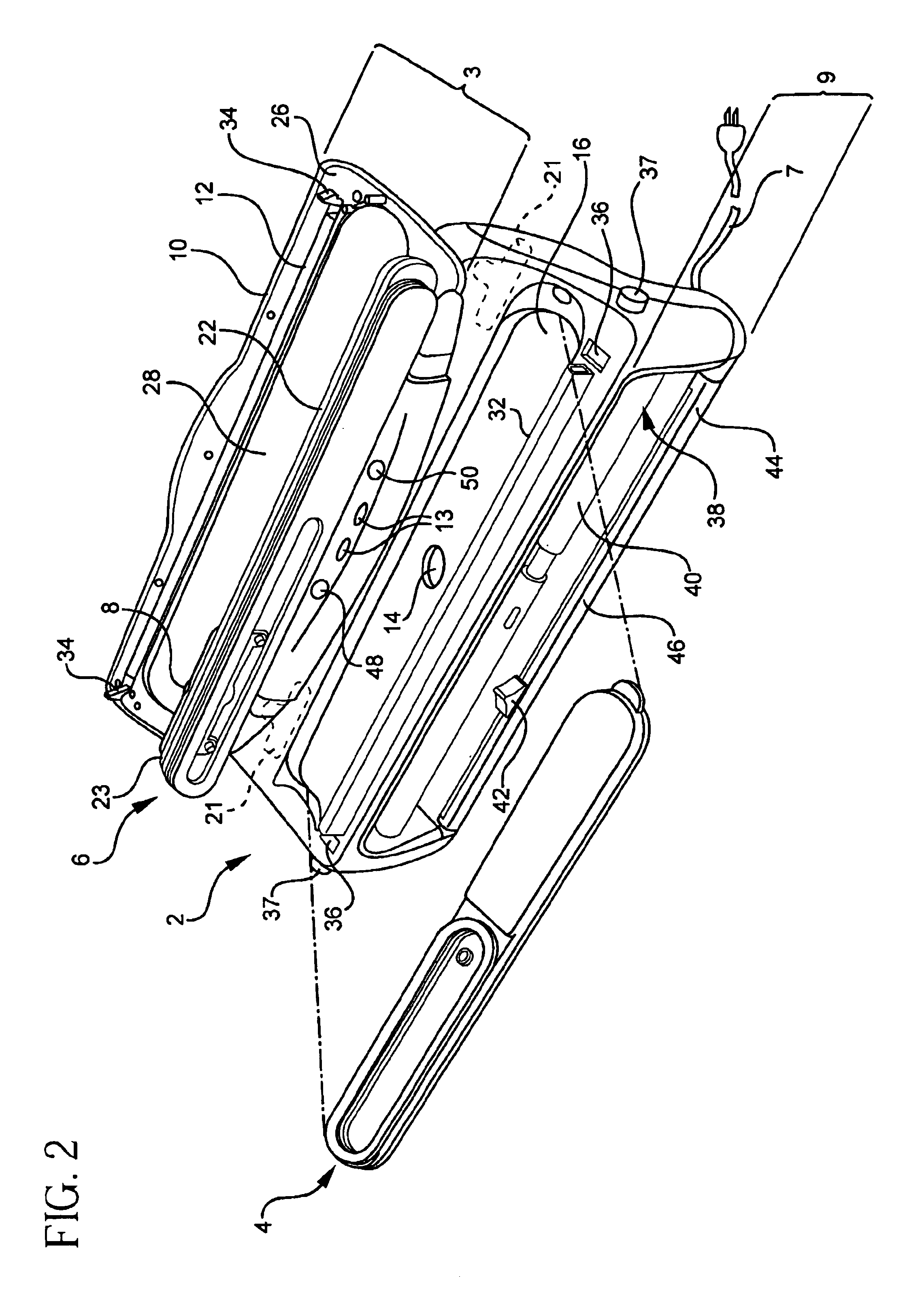
[0035]The vacuum sealing appliance 1, shown in FIG. 2, generally consists of a base housing 2; a bag-engaging assembly 3 having a pair of clamping doors; a sealing assembly 5; a power assembly 7; a plastic bag roll and cutting assembly 9; a status display 13; and a wall mounting assembly...


PUM


Abstract

A system for evacuating containers. The system includes a base housing defining a recess having a vacuum inlet port in communication with a vacuum source. An inner door is hinged to the base housing and is sized to cover the recess when in a closed position, and an outer door having a sealing member is hinged to close over the inner door. A vacuum nozzle extends at least partially between the inner and outer doors and is in communication with the recess. The inner and outer doors cooperate to retain a flexible container therebetween and around the nozzle so that the nozzle is positioned for fluid communication with an inside of the container. A removable drip pan is positioned to retain fluids drawn by the nozzle.

Description

[0001]This application claims the benefit of the filing date under 35 U.S.C. §119(e) of Provisional U.S. application Ser. No. 60 / 416,036, filed on Oct. 4, 2002, which is hereby incorporated by reference in its entirety.FIELD OF INVENTION[0002]This invention relates to packaging systems. More specifically, this invention relates to an appliance for vacuum sealing various types of containers.BACKGROUND OF THE INVENTION[0003]Vacuum sealing appliances are used domestically and commercially to evacuate air from various containers such as plastic bags, reusable rigid plastic containers, or mason jars. These containers are often used for storing food. Vacuum sealing food packaging provides many benefits with a particular advantage of preserving the freshness and nutrients of food for a longer period of time than if food is stored while exposed to ambient air.[0004]Typically, these appliances operate by receiving a bag, isolating the interior of the bag from ambient air, and drawing air fro...

Claims


Application Information

Patent Timeline
Patent Type & Authority Patents(United States)
IPC IPC(8): B65B31/00B65B31/02B65B31/06
CPCB65B31/06B65B31/046B65B51/146
Inventor PATTERSON, JUSTIN C.SIANO, SALVATORE R.MAK, CHI KIN JOHNJONES, HEATHERMARINO, FRANCIS E.BOSSA, DAVEOFFIR, YIGAL
Owner HOLMES GRP THE
Learn More