Transfer printing machine

Inactive Publication Date: 2006-02-28
DANSK HK
View PDF11 Cites 10 Cited by
  • Summary
  • Abstract
  • Description
  • Claims
  • Application Information

AI Technical Summary

Benefits of technology

[0012]According to a preferred embodiment, the endless belt is guided around a substantial portion of the periphery of the centre roller and through the nip between the pressure roller and the centre roller. As a result a reliable guidance of the pattern-carrying web and the textile web between the endless belt and the centre roller is obtained, and in addition to the local compression in the nip between the pressure roller and the centre roller a further comparatively weaker compression is obtained of the two webs across an increased portion. The latter can be advantageous in connection with the transfer of the pattern from the pattern-carrying web to the textile web.
[0013]The endless belt is preferably made of a waterproof, essentially non-stretchable material, whereby it is ensured that the pressure roller can subject the centre roller to a sufficiently high linear pres

Problems solved by technology

The transfer pattern printing and other types of roller processes are encumbered with the general problem of obtaining a uniform, linear pressure in the entire length of said rollers, i.e. in the entire width of the textile web, said width often being several meters.
This problem is caused by the rollers of one pair of rollers exclusively being supported at the ends.
In turn the latter causes a non-uniform transfer of the printed pattern from the pattern-carrying web to the textile web, said transfer often being insufficient in the middle.
This

Method used


Image

  • Transfer printing machine
  • Transfer printing machine

Examples


Example

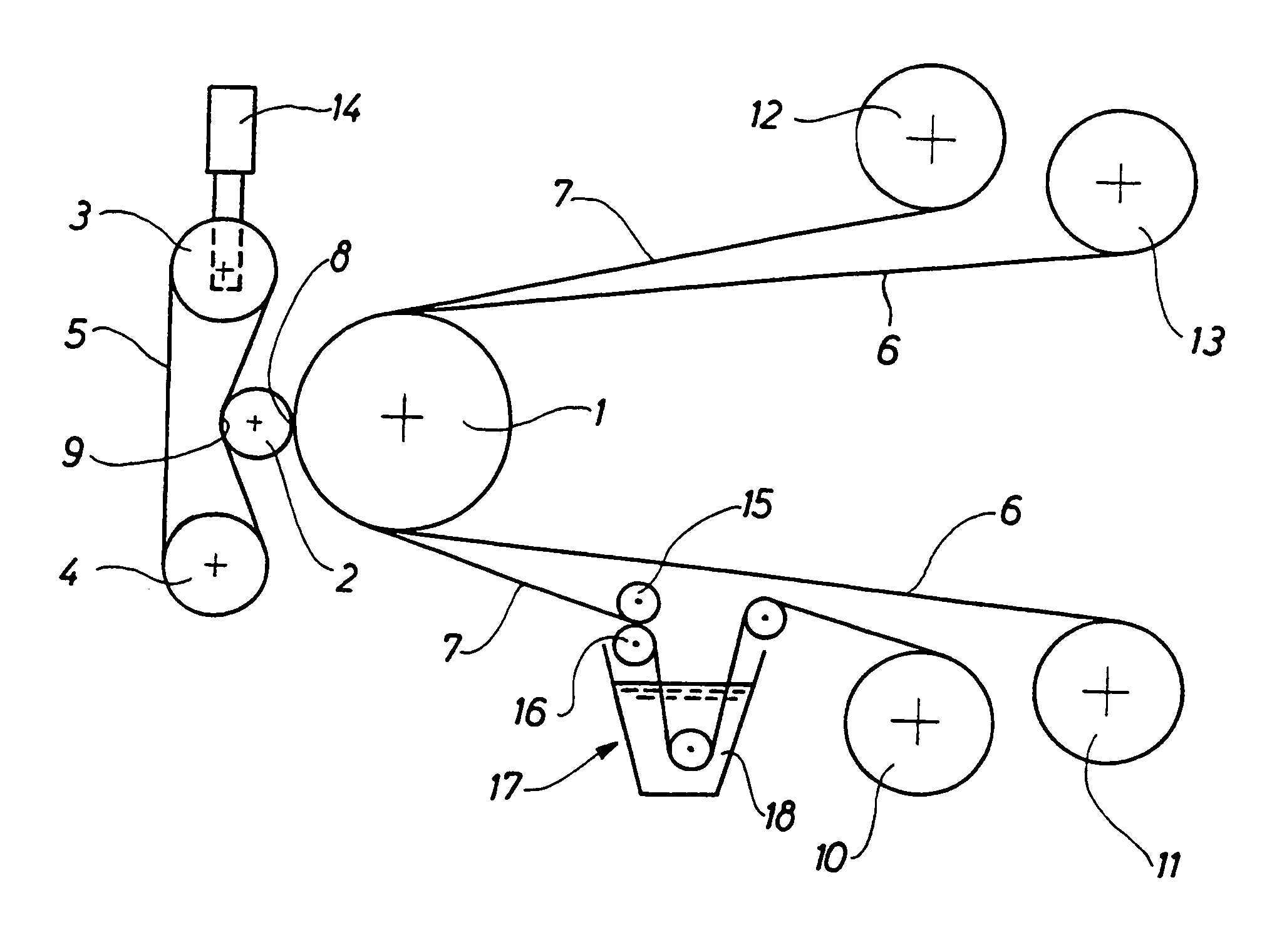
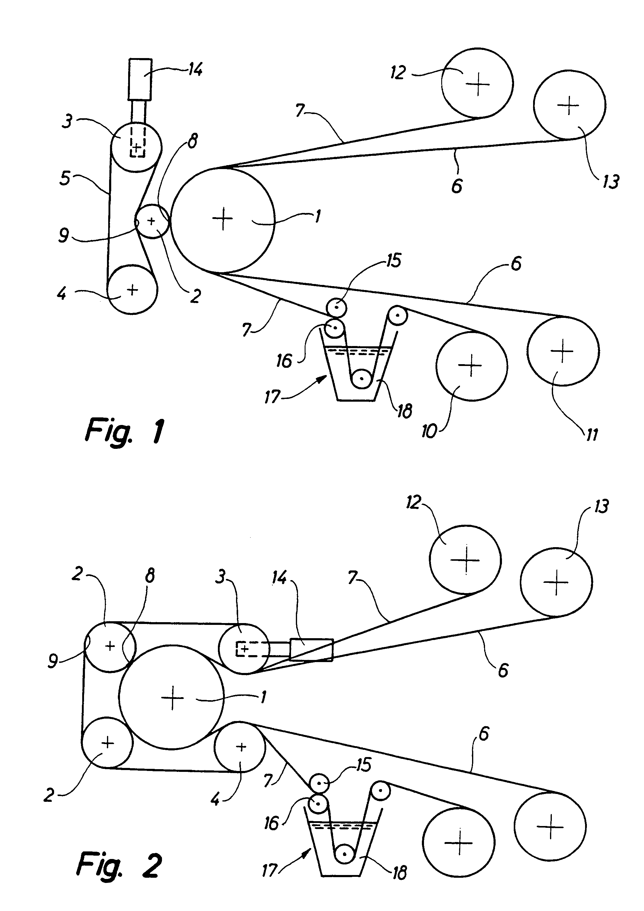
[0021]The machine shown in FIG. 1 for transfer pattern printing of a textile web comprises a centre roller 1, a pressure roller 2, a tension roller 3, a reversing roller 4 and an endless belt 5. A textile web 7 to be printed is wound off an unwind roll 10 and brought into contact with a pattern-carrying web 6. The pattern-carrying web is wound off an unwind roll 11 and guided into the transfer region between the pressure roller 2 and the centre roller 1. While passing from the roll 10 to the centre roller 1, the textile web 7 is carried through an impregnating unit 17 in which said web 7 is immersed in a fluid bath 18 and subsequently carried through a pair of rollers 15, 16 pressing as much fluid out of said textile web as possible whereby the resulting web contains an exactly defined residual moisture. The textile web 7 and the pattern-carrying web 6 are joined at a speed of up to 50 m / minute, preferably 10 to 20 m / minute, and carried between the centre roller 1 and the pressure r...


PUM

PropertyMeasurementUnit
Stretchabilityaaaaaaaaaa

Abstract

Machine for transfer pattern printing of a textile web, said machine comprising a centre roller (1), at least one pressure roller (2), a tension roller (3), a reversing roller (4) and an endless belt (5) which is of a width substantially corresponding to the length of the pressure roller (2). The endless belt (5) extends about the tension roller (3) and the reversing roller (4), and a first portion (8) of the periphery of the pressure roller (2) abuts and exerts a pressure on the centre roller (1). While in continuous contact with one another, a pre-printed pattern-carrying web (6) and the textile web (7) can pass between the centre roller (1) and the pressure roller (2) and here be subjected to a local compression. The endless belt (5) is guided around a second portion (9) of the periphery of the pressure roller (2), said second portion being positioned substantially diametrically opposite the first portion (8) of said periphery of the pressure roller, whereby the pressure exerted by the pressure roller (2) on the centre roller (1) is adjustable by an adjustment of the tension in the endless belt (5) by means of the tension roller (3).

Description

TECHNICAL FIELD[0001]The invention relates to a machine for transfer pattern printing of textile webs, said machine comprising a centre roller, at least one pressure roller, a tension roller, a reversing roller and an endless belt which is of a width substantially corresponding to the length of the pressure roller and which extends about the tension roller and the reversing roller, and where a first portion of the periphery of said pressure roller abuts and exerts a pressure on said centre roller with the result that a pre-printed pattern-carrying web and the textile web are subjected to a local compression, said preprinted pattern-carrying web and said textile web being in contact with one another and passing between said centre roller and said pressure roller.BACKGROUND ART[0002]Transfer pattern printing is a technique involving a continuous transfer of a pre-printed pattern from a pattern-carrying web to the textile web, where the two webs are continuously brought into contact wi...

Claims


Application Information

Patent Timeline
IPC IPC(8): B41F16/00B41F16/02B41F7/20G03G15/16B65C9/44D06P5/00D06P7/00
CPCB41F16/02Y10T156/1705
Inventor RASMUSSEN, KNUD VILLEFRANCE
Owner DANSK HK
Why Eureka
Try Eureka