Block baling press

a baling press and block technology, applied in the field of baling press, can solve the problems of considerable load on the baling, inability to knot the baling, and considerable productivity reduction, and achieve the effect of easy retrofitting

Active Publication Date: 2019-06-11
USINES CLAAS FRANCE
View PDF11 Cites 0 Cited by
  • Summary
  • Abstract
  • Description
  • Claims
  • Application Information

AI Technical Summary

Benefits of technology

[0008]To that end, the present invention provides a block baling press comprising a bale chamber with a baling ram that moves in the bale chamber in an oscillating manner in order to compress bale material, where an end face of the bailing ram that faces the bale material is divided into ram segments separated from one another by needle slots. At least a first needle slot is flanked by ram segments that have a profiling transverse to the first needle slot, which brings about a weaker compression of the crop in an edge region of the ram segments adjacent to the first needle slot than in a region of the ram segments spaced apart from the first needle slot.
[0009]By use of the inventive block baling press, the bale material is compressed in the bale chamber to form a compressed body in which zones of high compression and zones of low compression alternate across the width of the bale chamber. Given that the twine is placed around a zone having low compression and is knotted, the tension or friction to which the twine is exposed during the compression process is held relatively low despite a high mean density of the bale. Consequently, the risk that the twine will tear or slip out of its holder is reduced by use of the invention.
[0018]As an alternative, the spaced-apart region is formed separately from the ram segment, in particular, by a T-shaped or U-shaped profile joined to the ram segment. Such a profile has the advantage that conventional block baling presses are easily retrofitted with such a profile.

Problems solved by technology

The twine is thereby subjected to considerable loads with every compacting movement of the ram.
If this causes the twine to tear or slip out of its holder, the bale cannot be knotted.
The operation of the baler must be interrupted and the bale chamber must be emptied, which considerably lowers productivity.
Although the risk of tearing is reduced by using stronger twine, using stronger twine increases costs.
For that matter, the use of such strong twine makes it more difficult to subsequently cut open the bales.

Method used


Image

  • Block baling press
  • Block baling press

Examples


Embodiment Construction

[0025]The following is a detailed description of example embodiments of the invention depicted in the accompanying drawings. The example embodiments are presented in such detail as to clearly communicate the invention and are designed to make such embodiments obvious to a person of ordinary skill in the art. However, the amount of detail offered is not intended to limit the anticipated variations of embodiments; on the contrary, the intention is to cover all modifications, equivalents, and alternatives failing within the spirit and scope of the present invention, as defined by the appended claims.

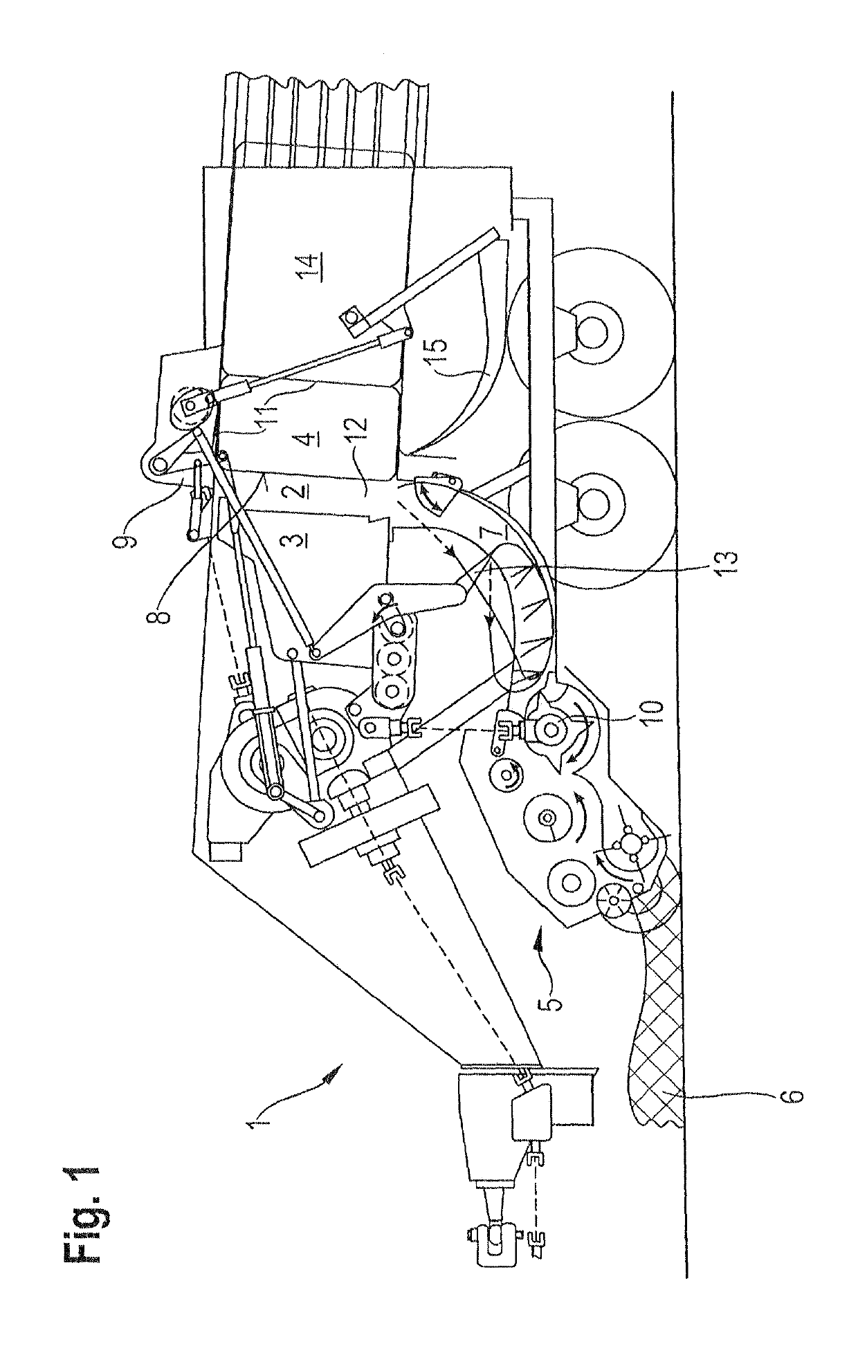
[0026]The baler 1, as shown in a schematic side view in FIG. 1, is designed as a trailer that is coupled to a non-illustrated towing vehicle and is driven by a P.T.O. shaft thereof. The baler 1 comprises a receiving device 5 (which is also referred to as a pick-up), for picking up crop 6 from the ground, a cutting device 10 for chopping the crop, a bale chamber 2 and a feed channel 7 that c...


PUM


Abstract

A block baling press has a bale chamber and a baling ram moveable in the bale chamber in an oscillating manner to compress bale material. An end face of the baling ram facing the bale material is divided into ram segments separated from one another by needle slots. At least a first needle slot is flanked by ram segments with a profiling transverse to the first needle slot. The profiling brings about a weaker compression of the bale material in an edge region of the ram segments adjacent to the first needle slot than in a region of the ram segments spaced apart from the first needle slot. Bales are obtained in which zones of high compression and low compression alternate across the width of the bale chamber. The bales are held together by twine placed around the zones having low compression.

Description

CROSS-REFERENCE TO A RELATED APPLICATION[0001]The invention described and claimed hereinbelow is also described in German Patent Application DE 10 2014 004 920.5, filed on Apr. 7, 2014. The German Patent Application, the subject matters of which is incorporated herein by reference, provides the basis for a claim of priority of invention under 35 U.S.C. 119(a)-(d).BACKGROUND OF THE INVENTION[0002]The present invention relates to a baler used to press agricultural crop such as straw, hay or silage into cuboid bales.[0003]Balers are known to comprise a bale chamber and a ram that moves in the bale chamber in an oscillating manner in order to compress bale material. Such a known baler is described in DE 10 2010 037 722 A1, for example.[0004]In order to ensure that crop is compressed in such a bailer retains its bale shape upon exiting the bale chamber, the bales in the bale chamber must be wrapped with twine and the twine must be tied into a knot. While the bale is being produced, the t...

Claims


Application Information

Patent Timeline
Patent Type & Authority Patents(United States)
IPC IPC(8): B30B9/30A01F15/04A01F15/08
CPCA01F15/046A01F15/042B30B9/3021A01F15/0825B30B9/3003A01F15/08A01F15/04
Inventor HESSELMANN, ULRICHSCHARF, THORSTENBIRKHOFER, STEFAN
Owner USINES CLAAS FRANCE
Why Eureka
Try Eureka