
Head gimbal assembly including a trace suspension assembly backing layer with a conductive layer formed upon a gimbal having a lower oxidation rate

a head gimbal and suspension assembly technology, applied in the direction of maintaining head carrier alignment, recording information storage, instruments, etc., can solve the problems of undesirable electrical discharge events between and the slider and the disk may not be desired

Active Publication Date: 2006-02-28
WESTERN DIGITAL TECH INC
View PDF8 Cites 70 Cited by
  • Summary
  • Abstract
  • Description
  • Claims
  • Application Information

AI Technical Summary

Benefits of technology

The present invention provides a head gimbal assembly for a disk drive that includes a trace suspension assembly backing layer, a gimbal conductive layer, and a slider. The assembly also includes a conductive compound for electrically grounding the slider to the trace suspension assembly backing layer. The invention also provides a head stack assembly for use with a disk drive that includes a flex cable assembly, an actuator, and a load beam. The invention also provides a method of manufacturing the head gimbal assembly and a disk drive including the head gimbal assembly. The technical effects of the invention include improving the performance and reliability of the disk drive.

Problems solved by technology

In particular, such close proximity of the slider to the disk may result in undesirable electrical discharge between the slider and the disk.
In practice, however, it has been found that despite the utilization of the conductive epoxy, undesirable electrical discharge events between the slider and the disk may nonetheless occur.

Method used


Image

  • Head gimbal assembly including a trace suspension assembly backing layer with a conductive layer formed upon a gimbal having a lower oxidation rate
  • Head gimbal assembly including a trace suspension assembly backing layer with a conductive layer formed upon a gimbal having a lower oxidation rate
  • Head gimbal assembly including a trace suspension assembly backing layer with a conductive layer formed upon a gimbal having a lower oxidation rate

Examples


Embodiment Construction

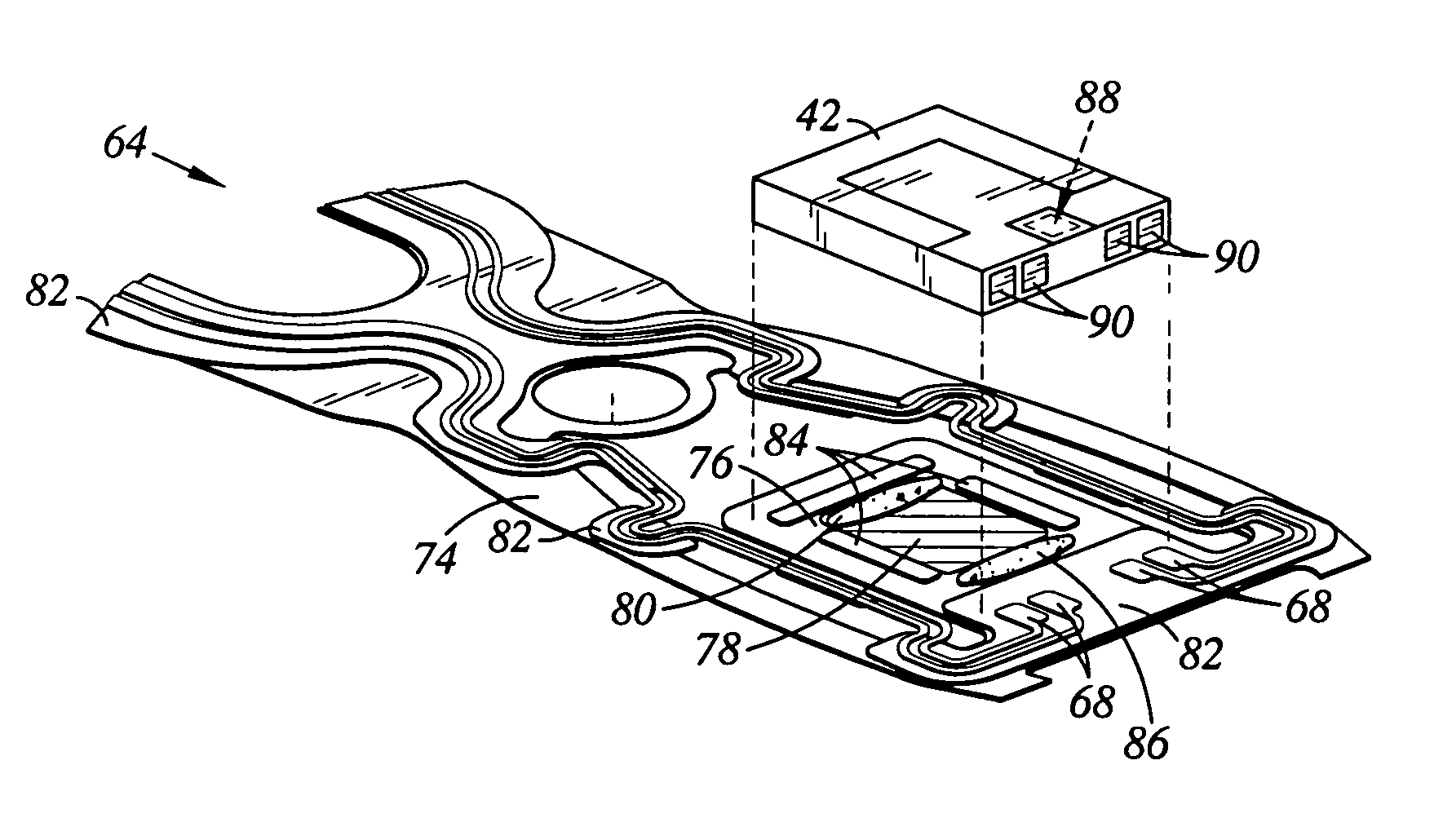
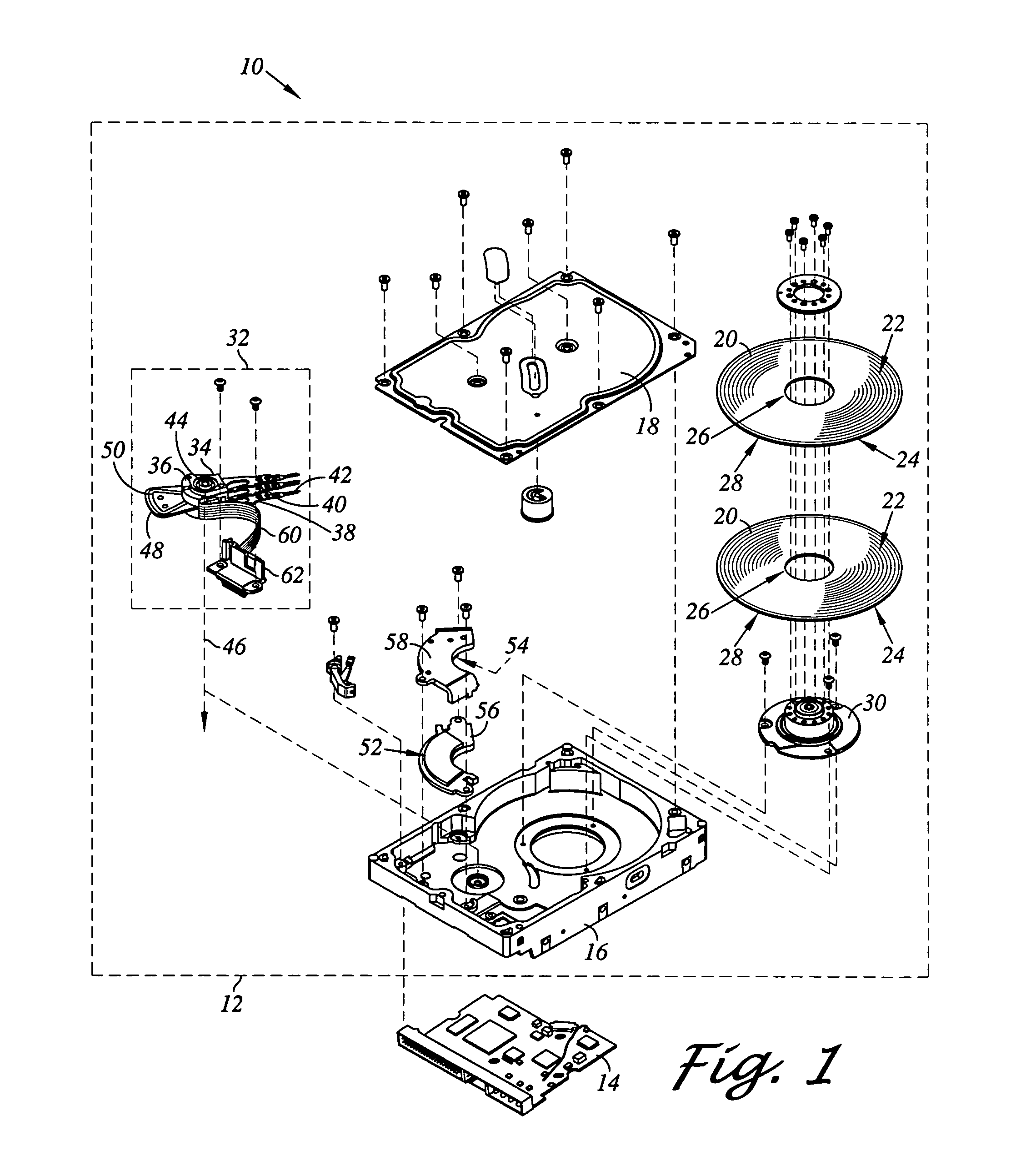
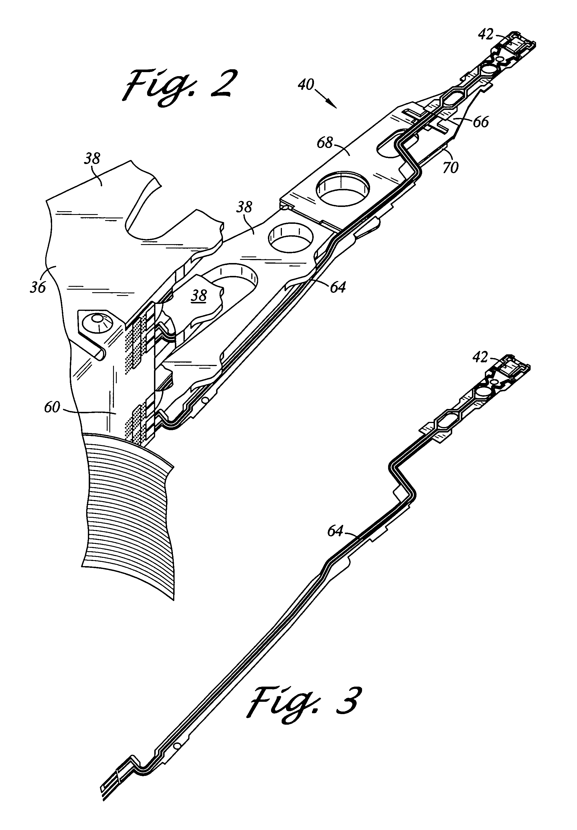
[0033]Referring now to the drawings wherein the showings are for purposes of illustrating preferred embodiments of the present invention only, and not for purposes of limiting the same, FIGS. 1–15 illustrate a disk drive including a head gimbal assembly and method of manufacturing the head gimbal assembly in accordance with aspects of the present invention.

[0034]Referring now to FIG. 1, there is depicted an exploded perspective view of a disk drive 10 as constructed in accordance with an aspect of the present invention. The disk drive 10 includes a head disk assembly (HDA) 12 and a printed circuit board assembly (PCBA) 14. The head disk assembly 12 includes a disk drive housing having disk drive housing members, such as a disk drive base 16 and a cover 18. The disk drive base 16 and the cover 18 collectively house at least one magnetic disk 20. While two disks 20 are shown, a single disk of multiple disks may be provided. Each disk 20 contains a plurality of tracks for storing data....


PUM

PropertyMeasurementUnit
conductiveaaaaaaaaaa
gimbal conductiveaaaaaaaaaa
areaaaaaaaaaaa

Abstract

A head gimbal assembly for a disk drive. The head gimbal assembly includes a trace suspension assembly backing layer including a gimbal. The trace suspension assembly backing layer is formed of a conductive material having a first oxidation rate. The head gimbal assembly further includes a gimbal conductive layer disposed upon the gimbal and formed of a conductive material having a second oxidation rate lower than the first oxidation rate. The head gimbal assembly further includes a slider supported by the gimbal. The head gimbal assembly further includes a conductive compound disposed between the gimbal conductive layer and the slider for electrically grounding the slider to the trace suspension assembly backing layer.

Description

BACKGROUND OF THE INVENTION[0001]1. Field of the Invention[0002]The present invention relates generally to disk drives, and in particular to a disk drive including head gimbal assembly including a trace suspension assembly backing layer with a conductive layer formed upon a gimbal having a lower oxidation rate.[0003]2. Description of the Prior Art[0004]The typical hard disk drive includes a head disk assembly (HDA) and a printed circuit board assembly (PCBA) attached to a disk drive base of the HDA. The head disk assembly includes at least one magnetic disk, a spindle motor for rotating the disk, and a head stack assembly (HSA). The spindle motor includes a spindle motor hub that is rotatably attached to the disk drive base. The hub has an outer hub flange that supports a lowermost one of the disks. Additional disks may be stacked and separated with annular disk spacers that are disposed about the hub. The head stack assembly has an actuator assembly having at least one transducer h...

Claims


Application Information

Patent Timeline
Patent Type & Authority Patents(United States)
IPC IPC(8): G11B5/60
CPCG11B5/4826G11B5/4853H05K1/0243H05K1/0215H05K2201/10969H05K3/305H05K3/321H05K2201/0347H05K2201/10727H05K1/056
Inventor SUBRAHMANYAM, JAI N.HUMBERT, PIERRE C.
Owner WESTERN DIGITAL TECH INC
Learn More