Unlock instant, AI-driven research and patent intelligence for your innovation.

Engine with a variable compression ratio

a compression ratio and variable technology, applied in the direction of connecting rods, bearings, shafts and bearings, etc., can solve the problems of weak vcr mechanisms, increased frictional loss,

Inactive Publication Date: 2006-03-07
SAKITA MASAMI
View PDF8 Cites 12 Cited by
  • Summary
  • Abstract
  • Description
  • Claims
  • Application Information

AI Technical Summary

Benefits of technology

[0008]An object of this invention is the provision of a VCR engine that does not cause movement of the engine head while the VCR mechanism is in operation.
[0010]An object of this invention is the provision of a VCR mechanism that does not excessively stress the engine frame.

Problems solved by technology

These VCR mechanisms, however, have weaknesses also.
In the engine invented by Ehrlich, the VCR mechanism adds extra inertia and friction-causing parts, and thus frictional loss must increase, especially at high-speed operation.

Method used


Image

  • Engine with a variable compression ratio
  • Engine with a variable compression ratio
  • Engine with a variable compression ratio

Examples


Embodiment Construction

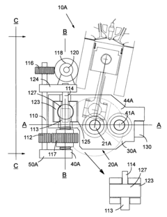
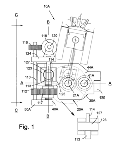
[0033]FIG. 1 is a cross-sectional view of an engine 10A equipped with a VCR mechanism of the preferred embodiment taken along D—D of FIG. 2. The engine 10A has a cylinder block with at least one group of bores, and each row of cylinder bores is longitudinally in line, and has at least one cylinder. The engine 10A has a driveshaft 41A through which the engine's output is transmitted to the externally located transmission, and a crankshaft 21A, which functions generally in the same manner as the crankshaft of any reciprocating engine except that its output must be transmitted to the driveshaft. The rotational axes of the driveshaft 41A and the crankshaft 21A are parallel.

[0034]The VCR engine 10A of the preferred embodiment generally comprises two crankshaft-driveshaft arm assemblies 30A, a driveshaft 41A, at least one crankshaft support plate assembly 30A′ (not shown in FIG. 1, but shown in FIG. 2), connecting beams 130, 142, and 122 (shown in FIG. 3), two jackscrew assemblies 40A, an...


PUM


Abstract

The engine is equipped with a crankshaft that is rotatably connected to pistons through connecting rods, and a driveshaft, which is used as the means for outputting the torque produced by the engine. The variable compression ratio mechanism of the preferred embodiment includes at least one crankshaft-driveshaft arm assembly, at least one crankshaft support assembly, and at least one jackscrew assembly. The crankshaft-driveshaft arm assembly ensures that the axis of the crankshaft when it is lifted will follow a circular arc with a fixed radius that centers the rotational axis of the driveshaft. The crankshaft-driveshaft arm assemblies and the crankshaft support plate assemblies are connected together by metal plates. A transmission assembly transmits the torque from the crankshaft to the driveshaft. The jackscrew assembly lifts up and down the crankshaft, and it does not require a locking mechanism.

Description

DOMESTIC PRIORITY[0001]This application is entitled to the benefit of provisional Applications: application No. 60 / 490,083 filed on Jul. 25, 2003; Application No. 60 / 511,833 filed on Oct. 16, 2003; and Application No. 60 / 513,391 filed on Oct. 22, 2003, all entitled “Engine with a Variable Compression Ratio.”FIELD OF THE INVENTION[0002]This invention relates generally to an internal combustion engine that operates with a variable compression ratio.BACKGROUND OF THE INVENTION[0003]The concept of an internal combustion engine with a variable compression ratio (VCR) has existed for more than 100 years. Probably the earliest U.S. Patent on a VCR was No. 651,966 by Fleury, issued in 1900. Since then, over 70 U.S. Patents have been issued on engines with VCR systems or on VCR mechanisms. In 2000, Saab displayed the SVC (Saab variable compression) engine in the Geneva auto show, and since then VCR has attracted enormous attention.[0004]The VCR engine displayed by Saab divides the engine int...

Claims


Application Information

Patent Timeline
Patent Type & Authority Patents(United States)
IPC IPC(8): F02B75/04F02B75/32
CPCF02B75/047
Inventor SAKITA, MASAMI
Owner SAKITA MASAMI