
Golf tee

a golf tee and tee technology, applied in the field of golf tees, can solve the problems of golf tee scattering or loss, inability to reduce shock resistance, and inability to use thin sheets of golf tees, etc., and achieve the effect of reducing shock

Inactive Publication Date: 2006-03-07
LEE CHANG ENTERPRISE
View PDF7 Cites 8 Cited by
  • Summary
  • Abstract
  • Description
  • Claims
  • Application Information

AI Technical Summary

Benefits of technology

[0006]Therefore, the present invention is made to solve such problems. It is an object of the present invention to provide a golf tee made of a thin sheet material to thus minimize shock so that a golfer hardly feels resistance when he or she hits a golf ball.
[0007]It is another object of the present invention to provide a golf tee integrated with a burying device in order to prevent the golf tee from being transformed when it is buried.

Problems solved by technology

However, golf tees made of thin sheets are not used.
Therefore, since almost golf tees are made of wood or light plastic whose inside is filled so as not to be transformed due to the applied pressure, it is not possible to reduce the shock resistance.
Furthermore, the shock resistance generated when the golfer hits the golf ball makes the golf tee scatter or lost.
Therefore, the golfer must make unnecessary efforts in order to collect the scattered golf tee and additionally carries supplementary golf tees for fear that the golf tee would be lost.

Method used


Image

  • Golf tee
  • Golf tee
  • Golf tee

Examples


Embodiment Construction

[0017]A golf tee according to a preferred embodiment of the present invention will now be described in detail with reference to the attached drawings.

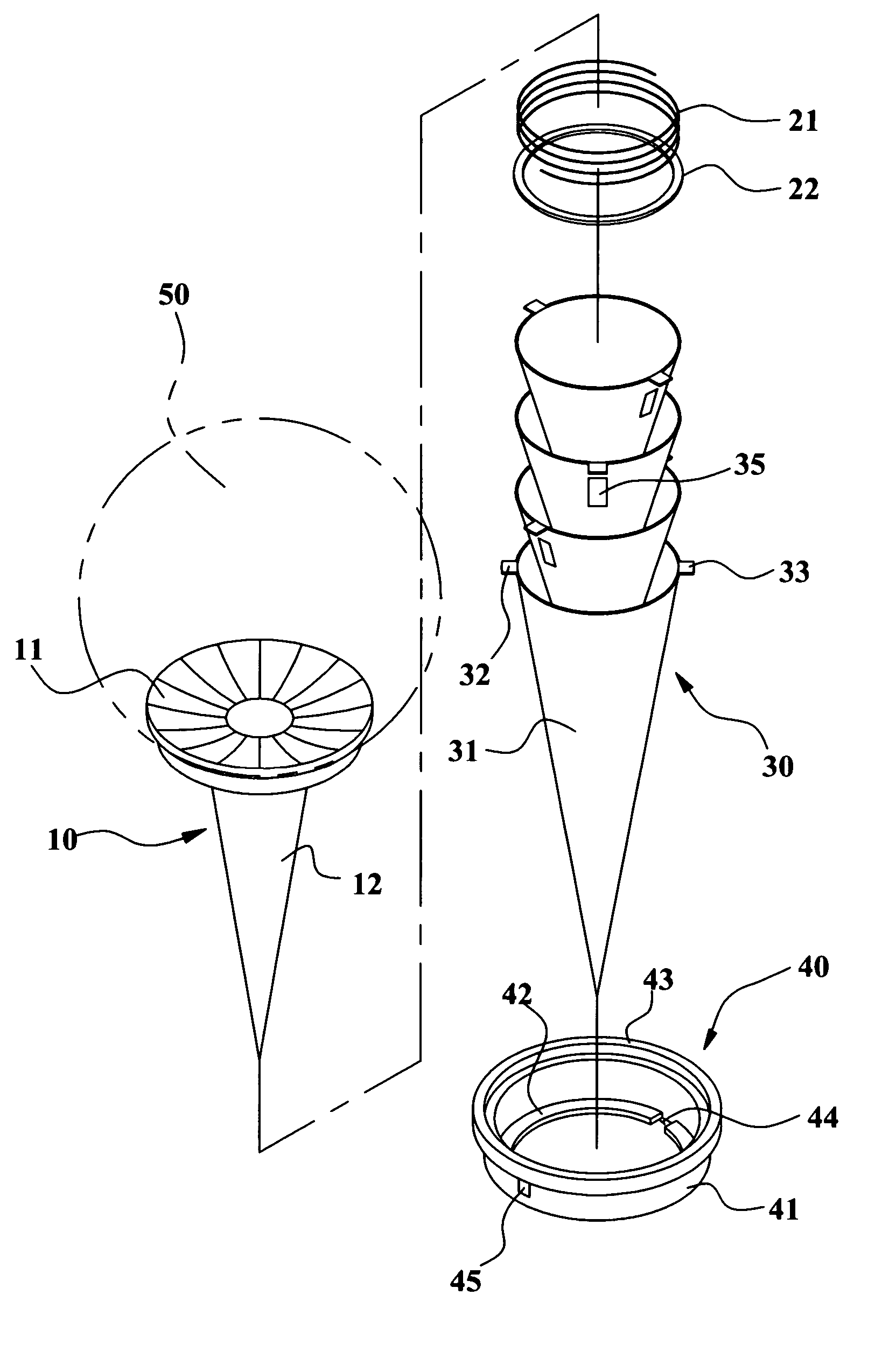
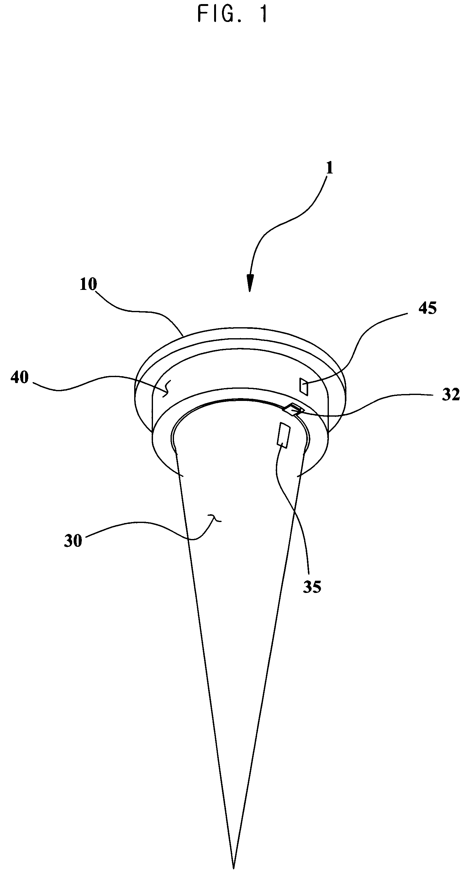
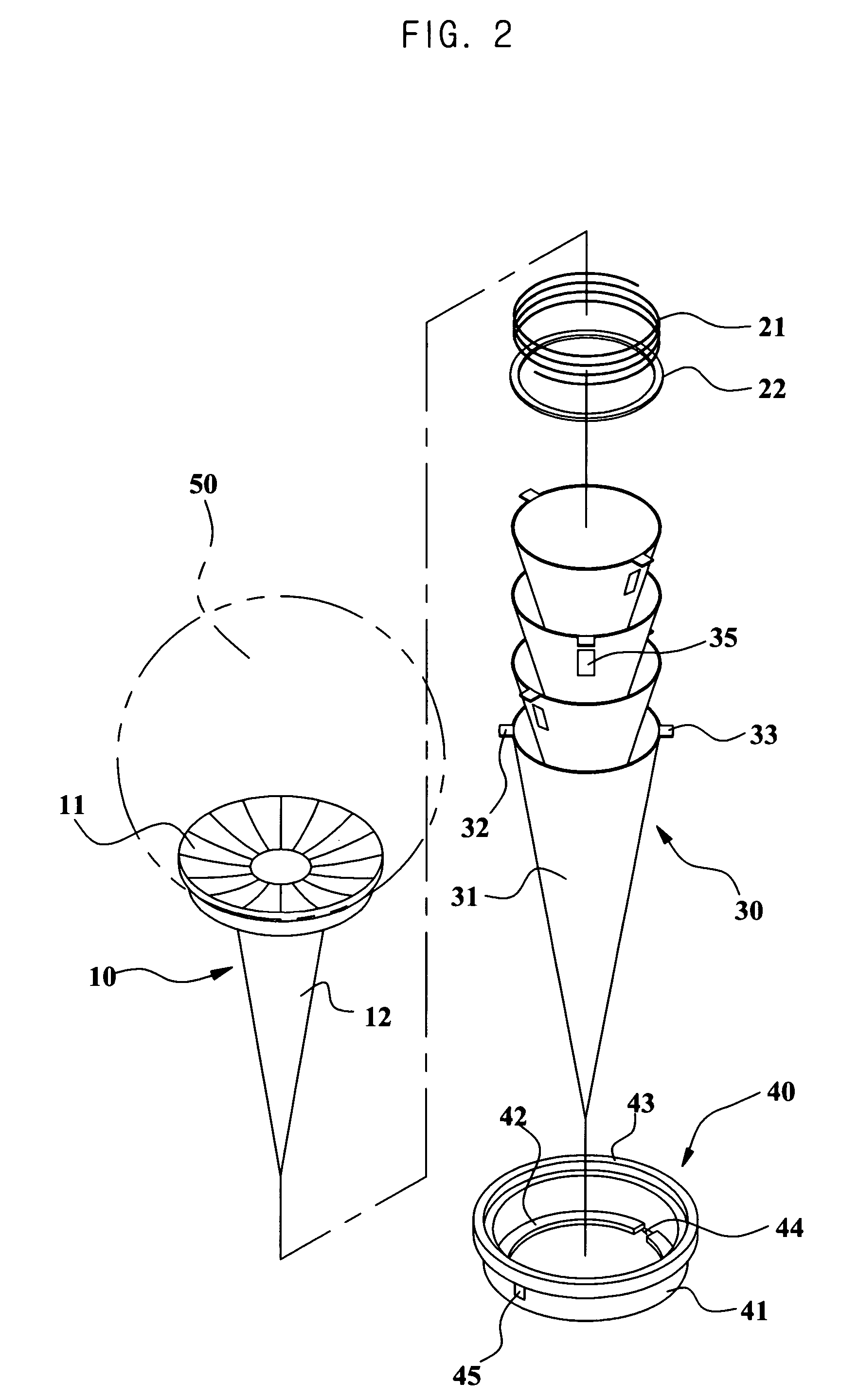
[0018]FIG. 1 is a perspective view illustrating a golf tee according to a preferred embodiment of the present invention. FIG. 2 is an exploded perspective view illustrating the golf tee according to the preferred embodiment of the present invention. FIG. 3 is a plan view illustrating that at least one inserting device is stacked in the golf tee according to the preferred embodiment of the present invention. FIG. 4 is a front view illustrating that at least one inserting device is stacked in the golf tee according to the preferred embodiment of the present invention.

[0019]As illustrated in FIGS. 1 and 2, a golf tee 1 according to the present invention includes a burying device 10 for generating pressure for burial, at least one stacked inserting devices 30 provided under the burying device 10, coupled with the burying device 10, and bur...


PUM


Abstract

A golf tee comprising a burying device including a concave head portion for retaining a golf ball, and a first cone extending from the head portion by a predetermined length. At least one stacked inserting device I provided which includes a second cone made of a thin sheet and arranged to receive therein the first cone of said burying device. At least one blocking protrusion is formed in an outer circumference of the second cone. A spring is compressed between said burying device and said at least one stacked inserting device. A coupling device is coupled with the burying device. The coupling device includes a cylindrical body with openings in an upper portion and a lower portion thereof sized for said at least one stacked inserting device to pass therethrough. A blocking jaw is formed in an inner circumference of said lower portion of the cylindrical body and arranged to engage said at least one blocking protrusion to block passage of said at least one stacked inserting device through the opening in said lower portion, and at least one groove is formed in the blocking jaw sized for said at least one blocking protrusion to be released from said blocking jaw when said at least one groove and said at least one blocking protrusion are coincidingly aligned with each other so that said at least one stacked inserting device can pass out of the opening in said lower portion under urging of said compressed spring.

Description

BACKGROUND OF THE INVENTION[0001]1. Field of the Invention[0002]The present invention relates to a golf tee, and more particularly, to a golf tee which is made of a thin sheet material to thus minimize the shock generated when a drive shot is performed so that a golfer hardly feels resistance and in which a plurality of inserting devices are stacked and with which a burying device is integrated so that it is not necessary to additionally carry a burying apparatus.[0003]2. Prior Art[0004]In general, golf starts in a tee ground that is a starting point of a game. At this time, a golfer buries a golf tee in a predetermined position of the tee ground, puts a golf ball on the buried golf tee, and performs a drive shot. When the golfer hits the golf ball, shock resistance is generated in a club head to thus deteriorate the hit sense of the golfer and to reduce a flying distance. Therefore, it is understood that the golf tee must be made of a thin sheet having small resistance. However, go...

Claims


Application Information

Patent Timeline
Patent Type & Authority Patents(United States)
IPC IPC(8): A63B57/00A63B57/10A63B102/32
CPCA63B57/0018A63B57/10A63B57/13
Inventor KIM, CHANG-HAK
Owner LEE CHANG ENTERPRISE
Learn More